2x2 Insulated Hardtop Enclosure Installation
Assembly instructions for all hardtop deck and patio enclosures that uses insulated aluminum panels supported by the 2" screen wall system.
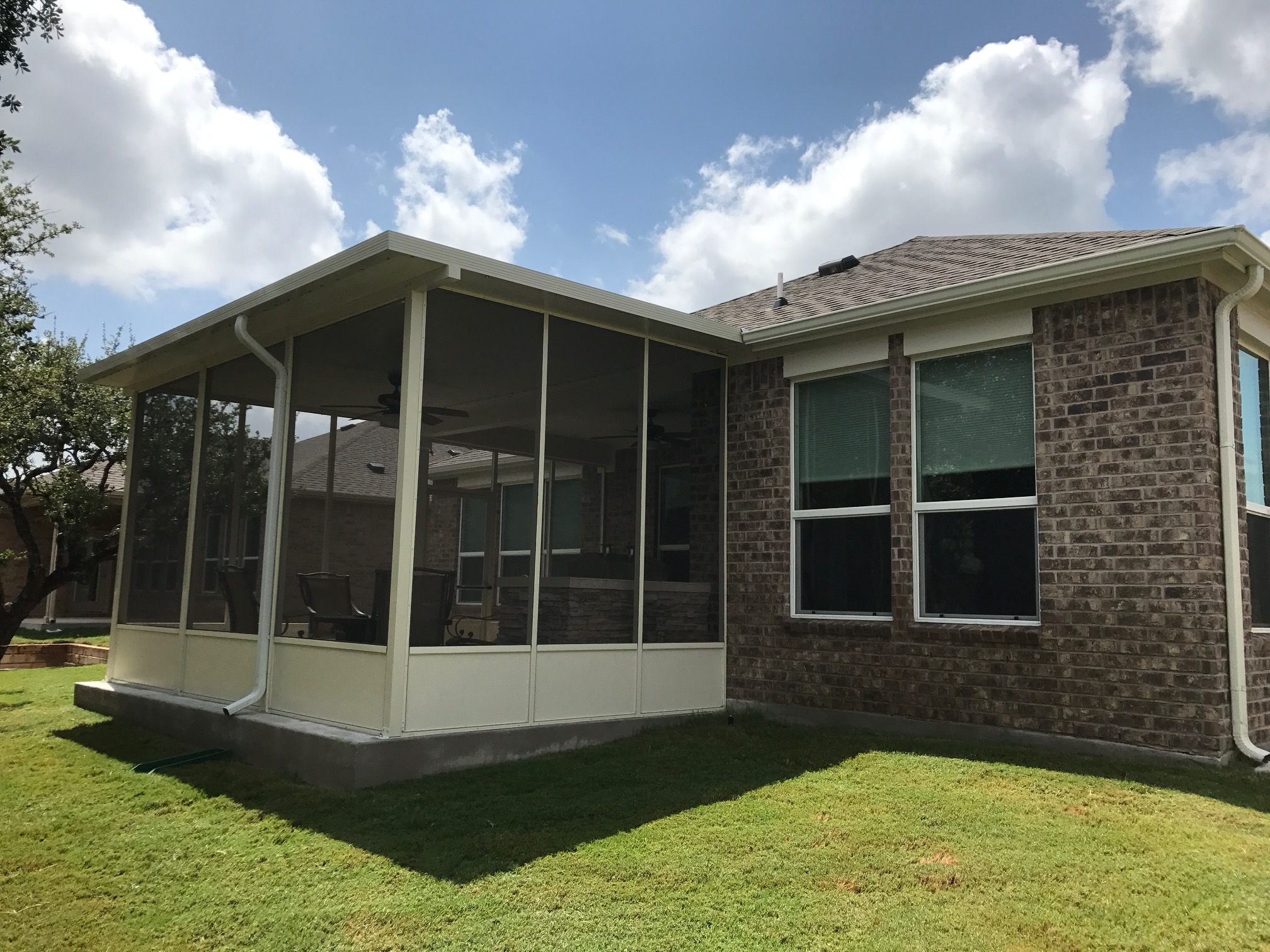
Thank you for purchasing a ScreenHouse
Hardtop Screened Deck Enclosure
Your purchase is designed and engineered by more than 20 years of commercial and residential design and proudly manufactured in the USA from responsibly sourced materials in the state of the art manufacturing facilities at Superior Mason and Four Seasons Building Products.
Your purchase is covered by the best warranty in the business with a limited 15 years warranty on the insulated panels and a limited lifetime warranty on all the aluminum extrusions.
DISCLAIMER**
This document is intended as a guide only. There are far too many variables within existing structures for us to address each an every one. As such, this kit is very adaptable and nearly any error is easily corrected within the existing materials received. Assembling this materials supplied kit will require patience & common sense. If you have any doubts about the action you should take we are just a call or email away for support. A reference cut sheet, 3D model and various drawings (plan view, roof view, elevation view, etc) are available in the customer portal or by request. We will not be responsible for errors in cuts made to the material.
PLEASE READ AND REVIEW COMPLETE INSTALLATION GUIDE STEP-BY-STEP
Installation Basics #
The Screen House Insulated top screened enclosure installation guide recommends 1-to-3 physically fit individual(s) with some experience in Do-it-Yourself (DIY) home projects and should complete installation within 2-4 days with proper planning.
Please review this installation guide thoroughly and understand each step’s task before the start of the installation process. All recommended tools are required for a successful installation and some components will require alterations to fit your structure’s unique installation. This installation guide is intended to be reviewed along with the custom layout for the room to be installed provided with your quote.
NOTE: There are several different configurations and installation methods. This guide is for a screened enclosure with aluminum insulated panel roof and using the 2x2 screen enclosure as the structure. If the supplied quote with your custom layout uses a beam and post due to the snow load, you have the the 2x3 wall structure or you have a flat pan roof, please refer to the correct installation manual for this type.
Inspect your project area for safety issues noting all electrical power lines and electrical outlets.
DO NOT begin this project until project area is safe.
Tools You Need
#Recommend and required tools are not included but necessary for a successful installation of this enclosure. Each structure and location is unique, so please review along with custom quote layout and call our team for support with any questions at 1.800.922.4760.
Tools
- 1-2 friends
- 4 ft. Carpenter’s level
- Carpenters square
- Chalk line (to mark “U” channel locations)
- Cordless drill/nut driver
- Caulking gun
- Chop saw with a metal cutting blade on it (required to make accurate and precision cuts)
- Ladders
- Masonry bits for drilling into concrete; masonry fasteners (if necessary)
- Metal file (to smooth cut edges)
- Hammer, Screwdrivers, Drill, tape measure, Box knife, Gloves, Safety eyewear
Materials
#Inventory all materials received in your shipment within a safe distance from the work area before you begin the installation process. Each step in this process will note components used to complete the task on each page. As these rooms are very custom, not all items below will be included with every order; however, a room specific materials list and cut sheet are available through the customer portal or on request by email.
Note: While every effort is made to keep this up to date, individual items may be replaced with equivalent new versions of the material at the discretion of the manufacturer and may not match up with items below. Please call or email our support team and we will review and provide guidance on the installation of the new material options. A "*" in the part number list below represents a designation for the color.
Roof Components
| Diagram | Part Number | Part Description | Dimension |
|---|---|---|---|
|
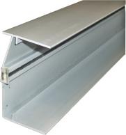
054810* (3")054825* (4")054830* (6") | Rear Header | 3-1/4" H x 24' L (3")4-1/4" H x 24' L (4")6-1/4" H x 24' L (6") |
|
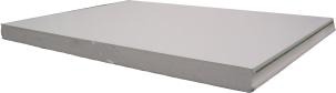
401317* (3")401500* (4")407085* (6") | 4' wide insulated panel w/o fan beam | 3" H x 48" W (3")6" H x 48" W (4")6" H x 48" W (6") |
|
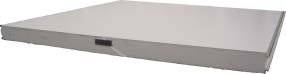
401318* (3")401501* (4")407087* (6") | 4' wide insulated panel w/ fan beam | 3" H x 48" W (3")6" H x 48" W (4")6" H x 48" W (6") |
|
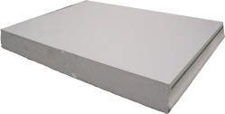
407080* (6") | 23" wide Insulated panel w/o fan beam | 3" H x 23" W (3")6" H x 23" W (4")6" H x 23" W (6") |
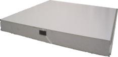
|
407081* (6") | 23" wide Insulated panel w/ fan beam | 3" H x 23" W (3")6" H x 23" W (4")6" H x 23" W (6") |
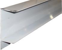
|
053370* (3")054030* (4") | Standard Side Fascia, Double Catch | 4" high x 25' long (3")5" high x 25' long (4") |
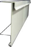
|
053385* (3")053465* (4")053470* (6") | Drip Edge Side Fascia | 4" H x 24' L (3")5" H x 24' L (4")7" H x 24' L (6") |
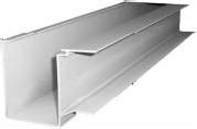
|
054015* (3")054030* (4") | Front Extruded Gutter, Double Catch | 4" H x 4" W x 24' L (3")5" H x 4" W x 24' L (4") |
Screen Wall Extrusions
| Diagram | Part Number | Part Description | Dimension |
|---|---|---|---|

|
1701* | Uchannel | .75" H x 2" W x (16' & 24') L |

|
1707* | 1" x 2" mainframe | 1" H x 2" W x (16' & 24') L |

|
1708* | 2" x 2" mainframe | 2" H x 2" W x (16' & 24') L |

|
1706* | 2" x 2" corner post | 2" H x 2" W x (16' & 24') L |

|
052590* | 1.5" x 2" uchannel | 1.5" H x 2" W x (16' & 24') L |
Screen Wall Components
| Diagram | Part Number | Part Description | Dimension |
|---|---|---|---|

|
1101* | 2" Mullion Clips | 1" x 1" x 2" |
|
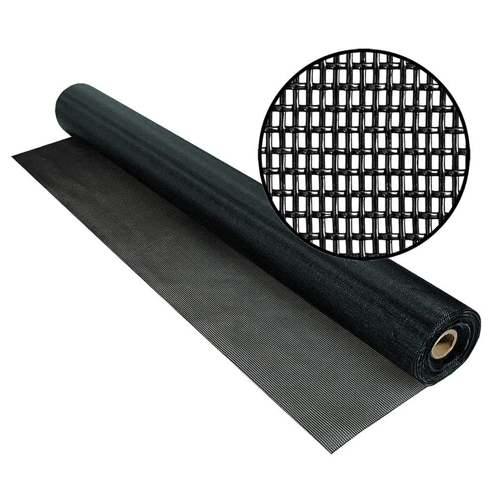
Varies by type | Screen roll | Width varies, 100' long |
|
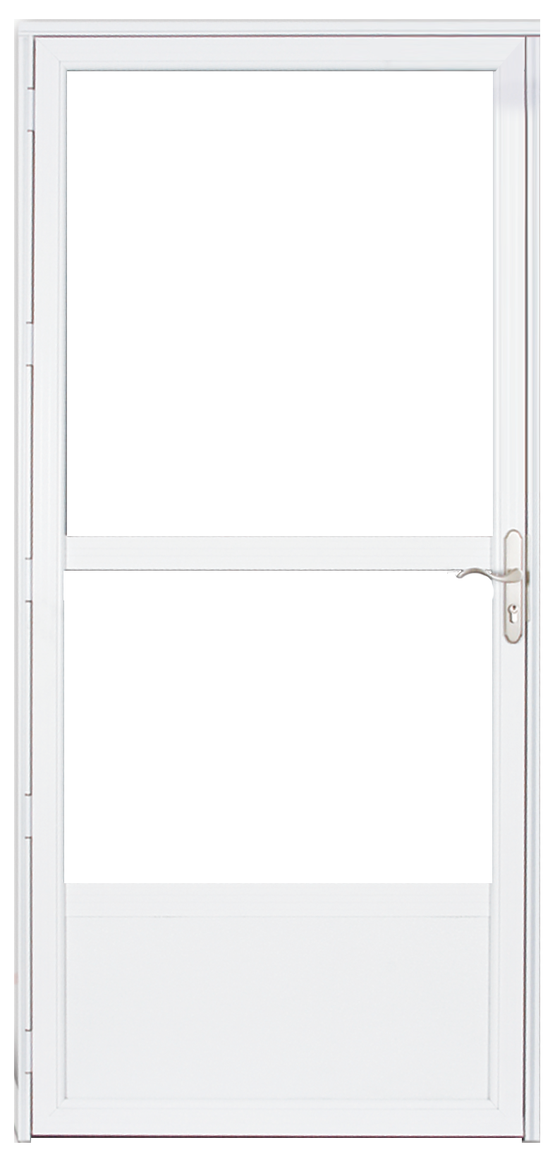
25* | Series 2600 Screen Door (assembled or knockdown) | 36" or 32" W x 80" W (standard) |
|
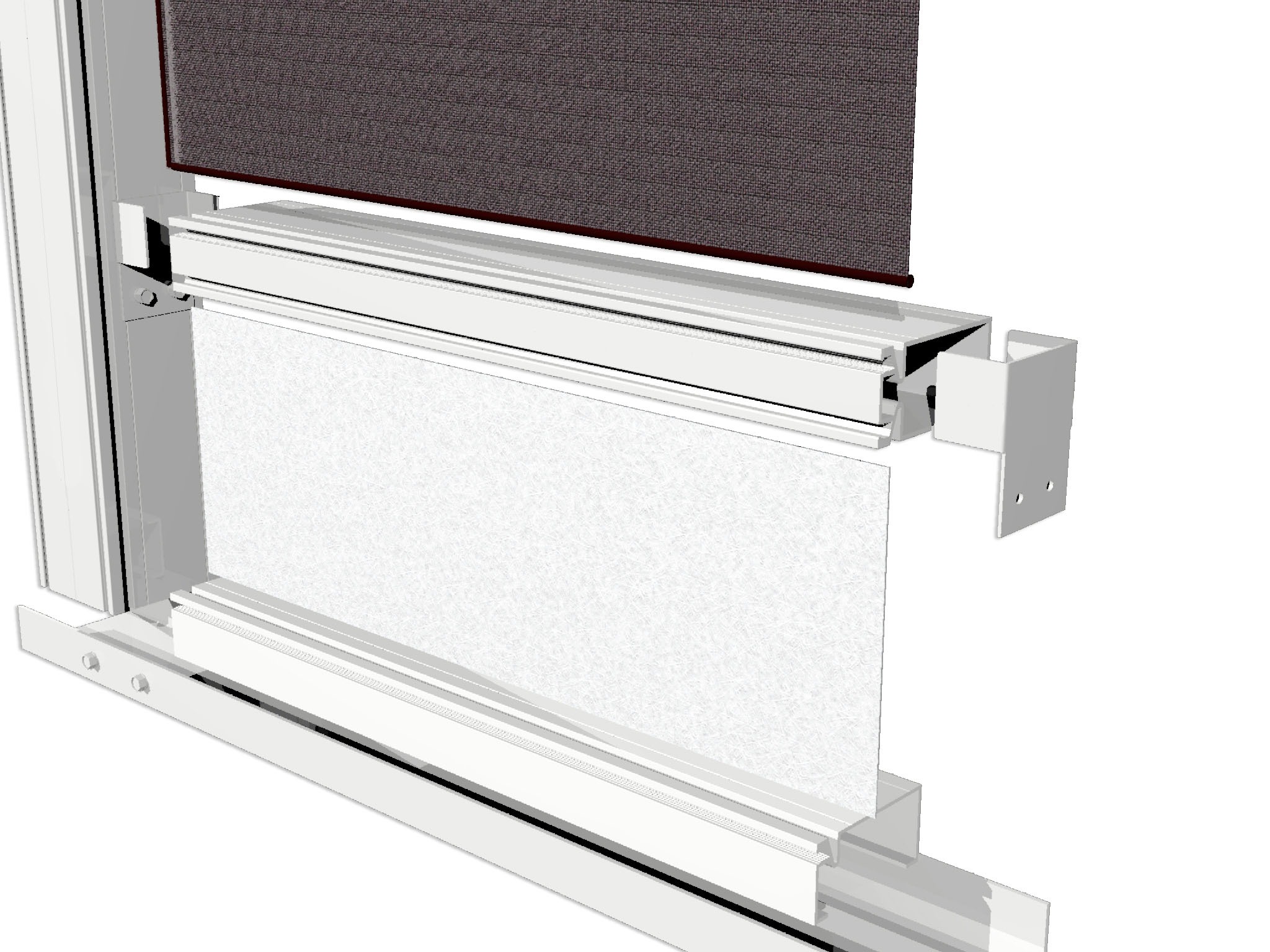
F250K* (18")047475* (24") | Embossed Kickplate | 18"H x 50'L24"H x 50'L |
|
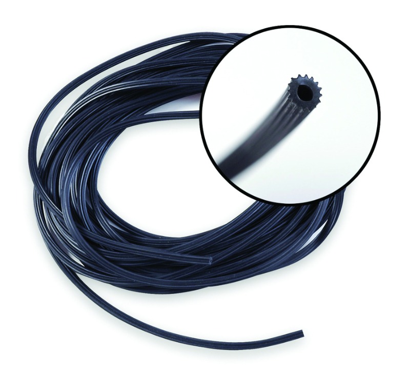
123-SD | Spline | .180" x 1500' |
|
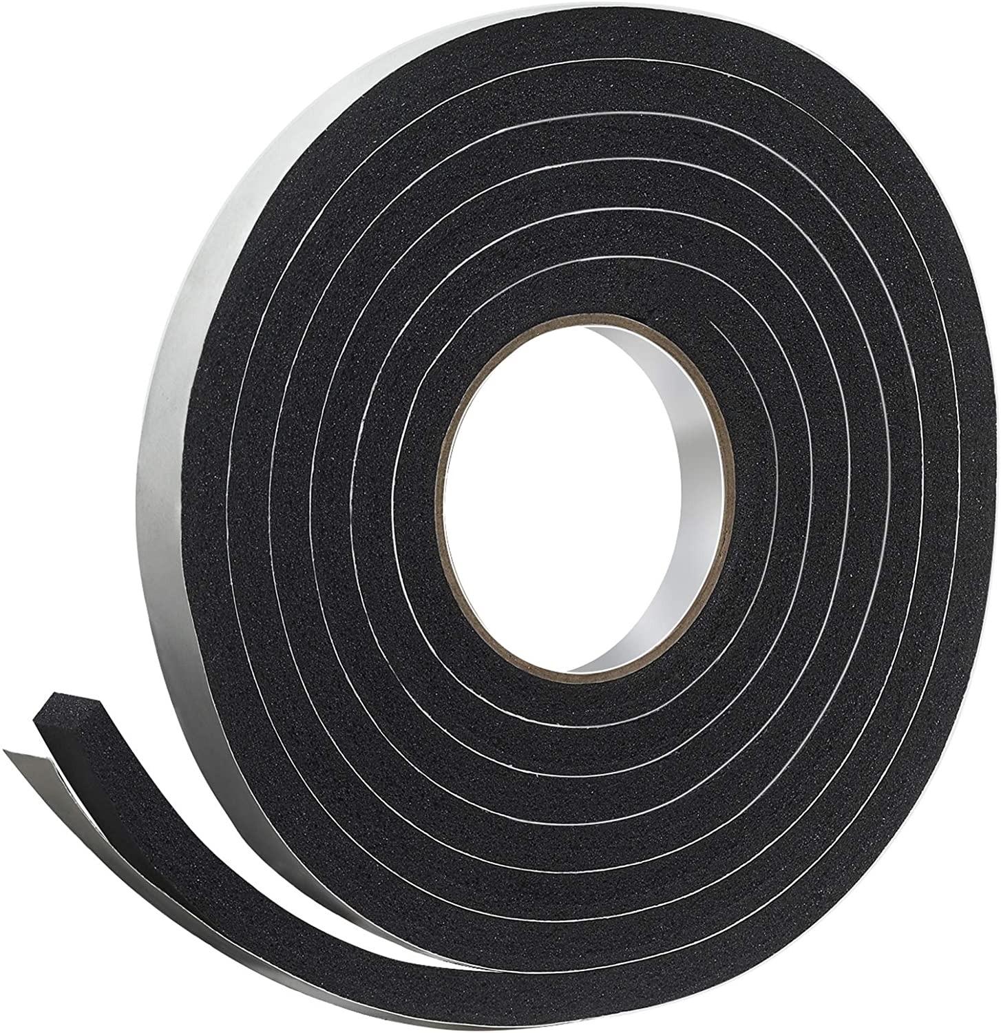
H310A0015 | Foam Tape | 1/2" W x 15' L |

|
P860* | Touch up paint | NA |
|
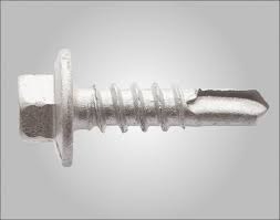
819536* | Color matched tek screw | #8 x 3/4" (100 per pack) |
|
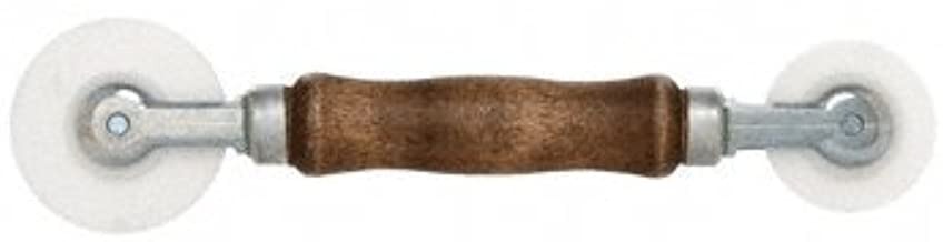
T410 | Heavy Duty Screen Roller | NA |
Roof Small Parts and Components
| Diagram | Part Number | Part Description | Dimension |
|---|---|---|---|
|
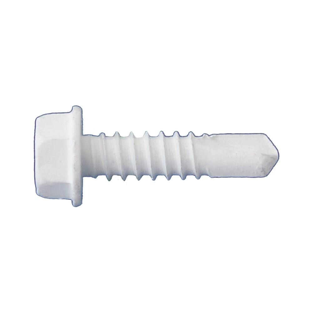
P405* | Painted Tek Screw | #13 x 3/4" |
|
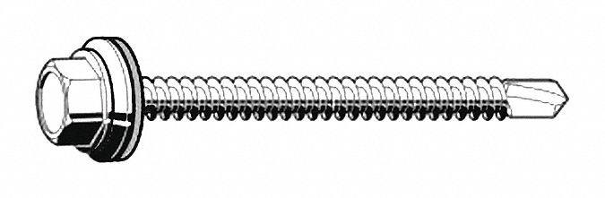
P431A0000P453A0005P455A0000 | Sealer tek with neoprene washer | 4" long (for 3" panels)5" long (for 4" panels)7" long (for 6" panels) |
|
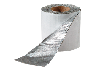
P602 | Peel and Seal Tar Tape | 50' roll |
|
P884 | Silicone Caulk | Tube |
| P521 | Drain Scupper | 3" x 12" |
Enclosure Assembly #
NOTE: For enclosures using 6" insulated roof panels, 3 sided drip edge fascia is supplied and a standard residential gutter system can be purchased locally.
Install Rear C Channel (wall header)
#Most insulated screen enclosures are supplied with a thermally broken c-channel which is a 24’ piece of extrusion with two legs and a black rubber thermal break in the middle of the back running the length of the extrusion. It can be installed in any orientation. The purpose of this is the reduce the thermal transfer from inside the room to the outside and reduce condensation that might occur. This may be substituted with an equivalent non-thermal pitched header in some southern regions. Follow the steps below to mount the header to your wall or fascia.
Determine C-Channel Location
#Determine the area in which you are going to mount the C channel. The channel can be installed on a wall or fascia, with or without a ledger board as shown in illustrations #1 to #3 below. The construction of your house will determine which option is best to ensure you can anchor the roof to structural elements.
- If you are installing on your fascia board make sure you are catching rafter ends in order to make a secure installation.
- If you are installing on your house wall or under the small gutter of your trailer / mobile home, it is suggested you install a ledger board by lagging it to your house wall studs on the inside of the exterior veneer. By doing this you can easily secure the C channel in as many locations as is necessary without worrying about finding house wall studs for each screw.
Mount C-Channel
#Once the wall or fascia is ready to mount the rear header, snap a level chalk line along the surface at which the bottom of your channel will be installed. Cut your C channel to the exact length of the finished size of your unit. Please note, this is the total width of all of your panels connected together minus the male lock of the last panel which you will trim off to install the side fascia extrusions.
Tip: The provided side fascia will cap the c-channel and the front extruded gutter. This will be the final step of the roof installation, but keep in mind that the fascia should be cut to the length of the panels + the width of the gutter and c-channel.
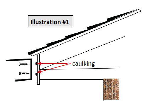
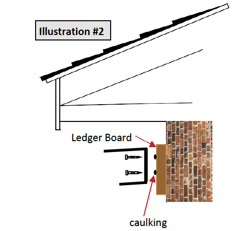
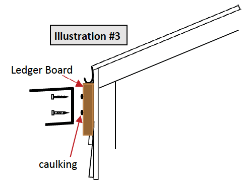
Prior to securing your C channel we suggest running two beads of caulking on the back surface where it will meet the building or fascia board. We suggest two screws (one above and one below the thermal break) every 12” . 16”. If you are installing on a fascia or wall without overhang protection (as in illustration #3 above), it is advised to flash over the channel and run a bead of caulk on the top of the C channel once installed so as to ensure a watertight seal.
The rear c channel is pre-pitched at 1/4" per foot. When determining your final post height or the front height of the screen enclosure, you will need to take this drop into consideration.
Tip: Though it is not “imperative” it is advisable that the C channel be installed with enough room to be able to use the supplied 1/2” hex head Tek screws on both the top and bottom lips in order to firmly hold the roof panels in the C channel at the house wall. If you cannot put the screws through the top lip, be sure to at least use the screws on the bottom lip.
You will be responsible for the purchase of the hardware (screws/lag bolts) required to secure the rear header to your existing surface.
Front Wall Installation
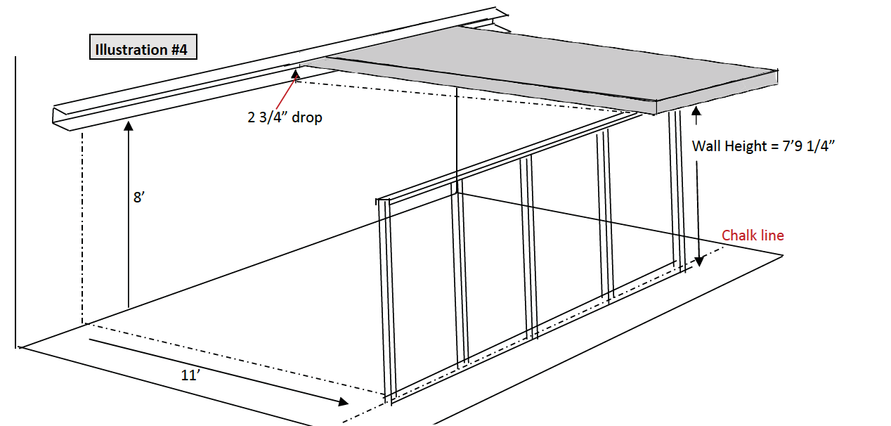
#During the quote process, a plan view wall layout and cutsheet would have been provided for your customer screen room which will show the dimensions (center-center) for the front wall posts. The following example is for a 12’ long, 3” thick panel supported at the 11’ mark by the screen wall assembly . Your numbers should be adjusted accordingly.
Between the guidelines given below and the drawing you received with your quotation you should have everything you need to assemble your unit. Before cutting anything, please lay out the material you have been given and understand how each piece is to be cut and placed, so that you know you have enough material to do the job. Always call before cutting if you are in doubt about anything and we can review in detail with you. Our hours of operation are posted at screen-house.com/contact.html for your convenience.
NOTE: When quoting a screen walls only system, we may optimize the material for best value and for safest shipping. Sometimes, the most efficient use of materials (due to the extrusions only being available in 16’ long and 20’ long standard lengths) will mean the end user will be required to butt splice certain screen enclosure profiles. Butt splicing will be the most common for top, bottom, and rear wall uchannel, c-channel and gutter.
Calculate Front Wall Height
#Take the measurement from the deck / patio to the bottom flange of the installed C Channel. For the purpose of this illustration, call it 8 feet. With a pitch of 1/4” per foot of projection, the total height of the post & beam assembly will be 8’ minus 2 3/4” (11 x 1/4”) = 7’ 9 1/4”. This means the total height of all your verticals (including H 120 corners) will be 7’ 9 1/4”.
Warning
Your wall placement MUST be square relative to the rear C channel assembly. One way to achieve this would be to temporarily insert one of your insulated panels into the rear C channel assembly exactly at the left edge and support it with ladders or wooden braces at the height that you have determined as per the instructions above.
"Square" up the awning perimeter by snapping chalk lines down the wall and plumb to the deck or patio surface where you will be attaching the screen walls. Run another chalk line perpendicular from the line on the wall out along the surface of the decking or patio. Measure the exact distance of the ‘on center’ point out to where your front screen wall is to be installed on each of those perpendicular lines and then snap a chalk line connecting those two points. You should be able to drop a plumb line from the underside of the roof panel at the ‘on center’ point of where the screen wall corner post will be installed and it should touch the line you have snapped on the deck or patio (blue circle in the drawing on the left. Make sure the measurement from corner to corner on the deck surface is exactly the same. This should give you a square installation.
Install Front Wall Uchannel
#Cut a piece of your 1" X 2" U channel running the full width of your front wall for both the top and the bottom. Attach it to the floor, making sure you are square to the backwall C channel installation per previous note. If your front wall includes a door placement, measure and mark where your door is to be placed. You will leave an opening that is exactly 36” wide (inside-inside measurement between verticals) in the bottom U channel installation for the door installation.
If you are mounting the U channel to concrete or brick, we would suggest using either Tapcon screws or drive anchors to secure the U channel to those surfaces. For all wood surface installation you can punch or drill a starter hole in the aluminum and use an appropriate size wood screw to secured the U channel. Though it is not necessary, you can, in order to waterproof the seal between U channel and floor surface, apply a bead of high quality silicone (screws and silicone purchased locally) to the underside of the U channel prior to securing it to the cement or wood surface.
NOTE: Since there are many different types and styles of house walls, or cement pads or wood decks you will need to supply your own screws/fasteners to attach the uchannel to your existing surfaces.
Install Front Corner Posts
#Set the corner pieces into the bottom Uchannel flush with the ends of your bottom U channel and screw them into place. Two tek screws through the lip of your U channel to the H120 both inside and outside.
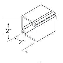
It is likely that you have been provided with 1.5" X 2" for your top U channel. Check and make sure you have enough to run on top of both side walls and the front wall. If not, save them for the side walls as they make installing verticals on the sloped sides a bit easier. Use the standard 1" x 2" U channel in its place in this case. Cut a piece the full width of the room and set it on top of your two corner posts and screw it into place just as you did on the bottom. If the width of the room exceeds 20', it will be necessary to butt splice uchannel together to cover the full width.
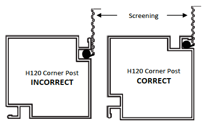
Install Front Wall Verticals
#The custom drawing provided during the quotation stage and available in the customer portal will identify the number of verticals you are to use on the front wall, which may even include a door placement. Cut the number of verticals you need and install them in the same manner as the corner posts screwing through the U channel lips, two tek screws each both top and bottom, inside and outside.

If your door installation is on the front wall at a corner you will want to set your H120 corner post in the side wall bottom U channel per below.
Insulated Panel Installation
#With your front screen wall and rear header in place, it is time to start installing the insulated roof panels. We recommend you start on the Left Hand Side (LHS) "outside looking in” (OLI) toward the house wall and the instruction that follow are based on that orientation. However, if there are obstructions or you are attaching the roof to an L-shaped space with two walls attached, starting from the right side also works. If there are fan beam panels in your order, be sure the side with the fan beam is facing down into the room.
NOTE: In the case of an L-shaped or U-shaped installation, you may be provided with non-pitched header for the side wall(s), provided this information was given during the quotation stage. This header (or standard fascia, if not provided) should be mounted to the side walls prior to installing the first panel.
Determine The Best Panel Layout
#Insulated panels come in both 4' wide and 2' (23" wide, technically) wide configurations. Generally, 4' wide panels are sent where possible; however, depending on the dimensions, you may receive a combination of both to fill the order. If panels are the same size and there are no fan beams, there is no special consideration. If one or more 2' wide panels are sent, you may want to consider the symmetry of the panels (and seams) into account. For example, and 18' wide cover would have (4) x 4' panels and (1) @ 2' wide panels. The optimal layout for most, would put the 2' wide panel in the middle and then two 4' wide panels on each side of it.
For covers that include one or more fan beam panels, additional planning is important. On panels purchased with this upgrade, a reinforced conduit runs the full length of the panel to supply power and mount a light or fan while concealing the wiring. These beams are located in the center of a panel and may take some additional work to be centered within the enclosure (or symmetrically placed in the case of multiple fan beams). For odd quantities of panels, its normally easier as the fan beam panel can be centered by nature of the design (ie. a cover with 5 panels can have the fan beam centered with 2 panels on either side).
For a cover with an even number of panels, you can either decide to have the fan beam off center or you will need to rip one of the non fan beam panels in half and then use the two halves as the first and last panels, respectively. For example, on a 16' wide cover, the only way to center the fan beam would be to take one of the 4' panels and rip it down the middle - one 2' piece becomes the first panel (with the cut edge into the fascia) and the 2nd half is the last panel, again with the cut edge into the fascia. For cover installations starting from the left, the half with the male lock should be used as the first panel.
Be sure to mark the location of the fan beam before capping the end with the fascia gutter so it is easily located when you get to installing the fan or light fixture.
NOTE: At the discretion of the manufacturer, they may send one or more panels that are longer than the projection requested for the room. This is normally done to fulfill orders faster since the panels can quickly and easily be cut back on site using the tools listed above. Simply cut the aluminum on each side of the panel with
Install the First Panel
#With the female lock on the left, lift your panel into place. We recommend putting a bead of caulking on the underside of the top lip of the backwall C channel prior to pushing the panel into place.
TIP: In order to avoid scratching the underside face of the roof panel use cardboard or a soft fluffy cloth on top of the beam or screen wall until you are ready to secure the panel in place.
Once the panel is in place, flush with the left edge of the backwall C channel, secure the panel to the C channel using the 3/4” hex head self tapping Tek screws on both top and bottom flanges, roughly every 8”.
Out front where the panel sits on the screen wall, you will be supplied with large self sealing hex head lag screws with neoprene back metal washers, 1” longer than the thickness of the roof you are installing. We suggest installing (1) lag screw on the Right Hand Side (RHS) of the panel 5” in from the seam. DO NOT TIGHTEN ALL THE WAY DOWN SO THAT THE NEXT PANEL HAS ROOM TO SNAP ONTO THIS PANEL. This will hold the panel in place while you assemble the remainder of the roof.
TIP: As you install the rest of the roof tighten the lag screw/bolts so as to create a slight dimple in the top of the roof metal. It does not need to be tightened any more than that! We also recommend a large bead of caulking on top of each lag screw so as to prevent a water build up in the “dimple.”
Install Remaining Panels
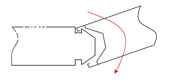
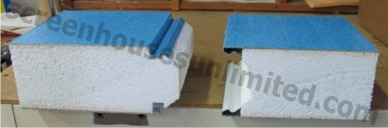
#With the first panel in place, put a bead of caulk on the underside of the top lip of the C channel, put your cloth or cardboard on the beam or front screen wall and put a bead of caulking (supplied) in the top channel of the male lock making sure it is a consistent thickness and with no air pockets. Then take your second panel, position it just outside the C channel, raise it up and gently but firmly, snap it down. Pushing from the front of the cover to toward the house, slide it into place in the C channel. Be sure to do this before the caulking begins to set! Wipe off any excess caulking on the seam. You may secure the panel to the C channel using the 1/2” hex head self tapping Tek screws on both top and bottom flanges, roughly every 8”.
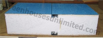
Tip
If you have panels with a fan beam included, you are best served to run the wiring through the rear header and into the panel beam prior to securing the panel into the header.
Trim and Install Last Panel
#Your last panel will have a male lock protruding past the edge of the roof line. Prior to putting into place, carefully trim off the male lock back to the seam edge. The seam edge should line up with the right hand edge (OLI) of the C channel installed on the house wall. This will also allow you to attach the extruded side fascia, capping the edge of the insulated panel.
Secure Panels to Uchannel
#To install the remaining lag screws, snap a chalk line on top of the roof that is centered over your screen wall. Be sure that it runs over top of the center of the first lag screw you installed in the first panel. Using the chalk line as a guide, install the remain lag screws/ bolts. We suggest putting a bead of caulking down around the lag screw/bolt prior to finally tightening it down on the roof.
You will use (3) three lag screws/bolts on every 4’ wide panel and (2) on every 2’ wide panel. Always be sure the outside lag bolts/screws are at least 5” in from the seam edges.
NOTE: It is normal for the lag screw to extend down through the uchannel on the underside of the roof. There is no need to cut them off as they will be covered by the 1x2 mainframe that will be installed in the uchannel in a later step.
Finishing Your Roof Installation
#Before going any further, take your side fascia extrusion and bring it up to the end of your front gutter extrusion to understand how they are going to fit together on your roof. As noted previously, the side fascia will cap both the back wall C channel as well as each end of your front gutter.
NOTE: For 6" panels, drip edge fascia is provided for all three sides, so there is no gutter to cap at the front. Instead, the sides butt against the front and then the joint is caulked.
Cut and Install Front Gutter
#
Tip
When installing the gutter over the panels, be sure the panels sit square inside the channel. If not installed properly, the gutter will install at an angle and will not be capped properly by the side fascia.
Cut and Install Side Fascia
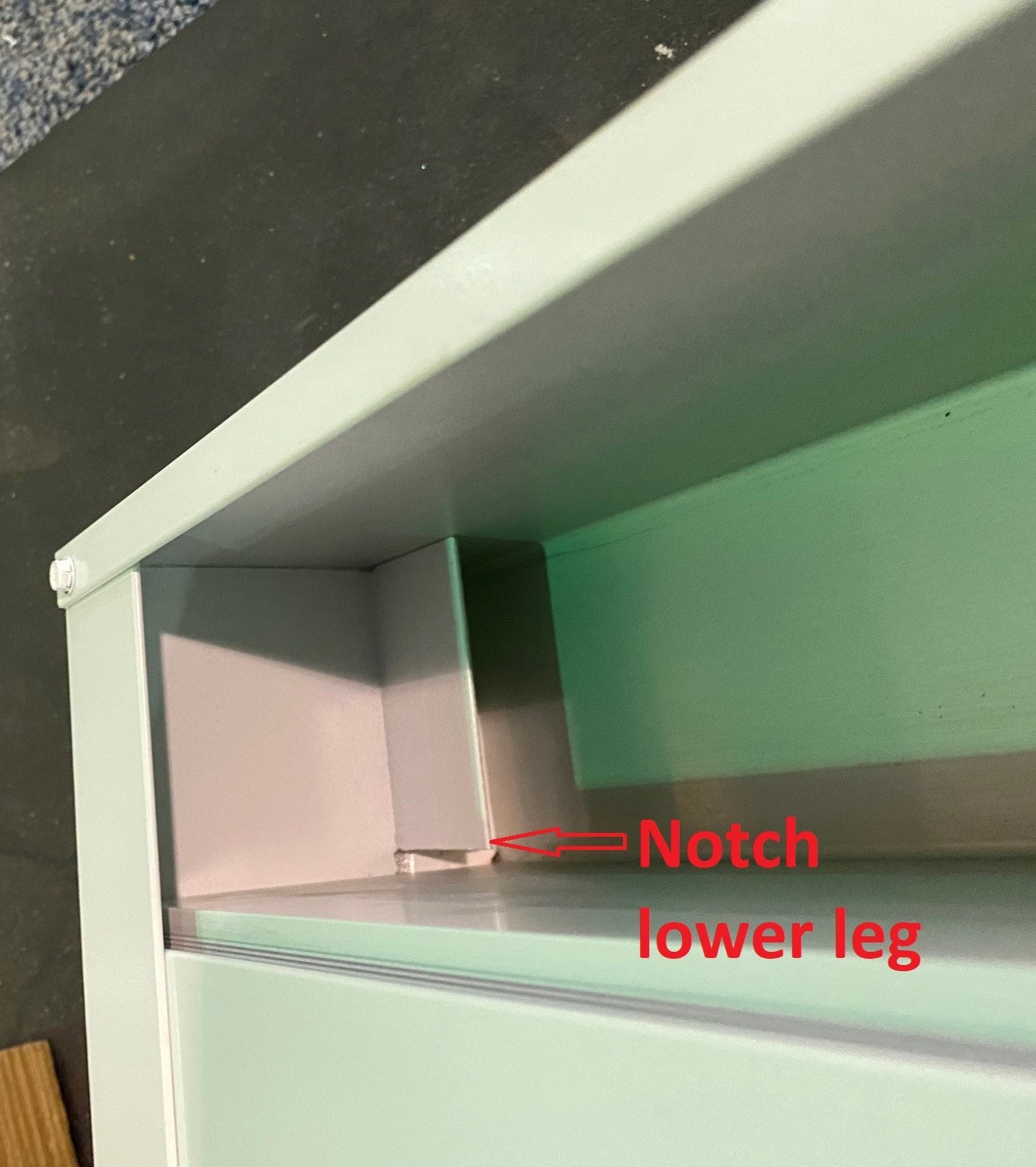
#Next cut the exact length of side fascia you need to run from the house wall to the front gutter, capping the end of the gutter itself. The double catch fascia is installed with the lip oriented on the bottom so it caps the gutter which drops below the panel line.
In order to accomplish this, the lower leg that mounts to the panels will need to be notched where it meets the gutter as shown in the photo to the side. Again put a bead of caulking on the underside of the top lip before you slide it in place on the side of your roof panels. Use the 1/4” self tapping Tek screws to attach the top and bottom flanges to your roof panels.
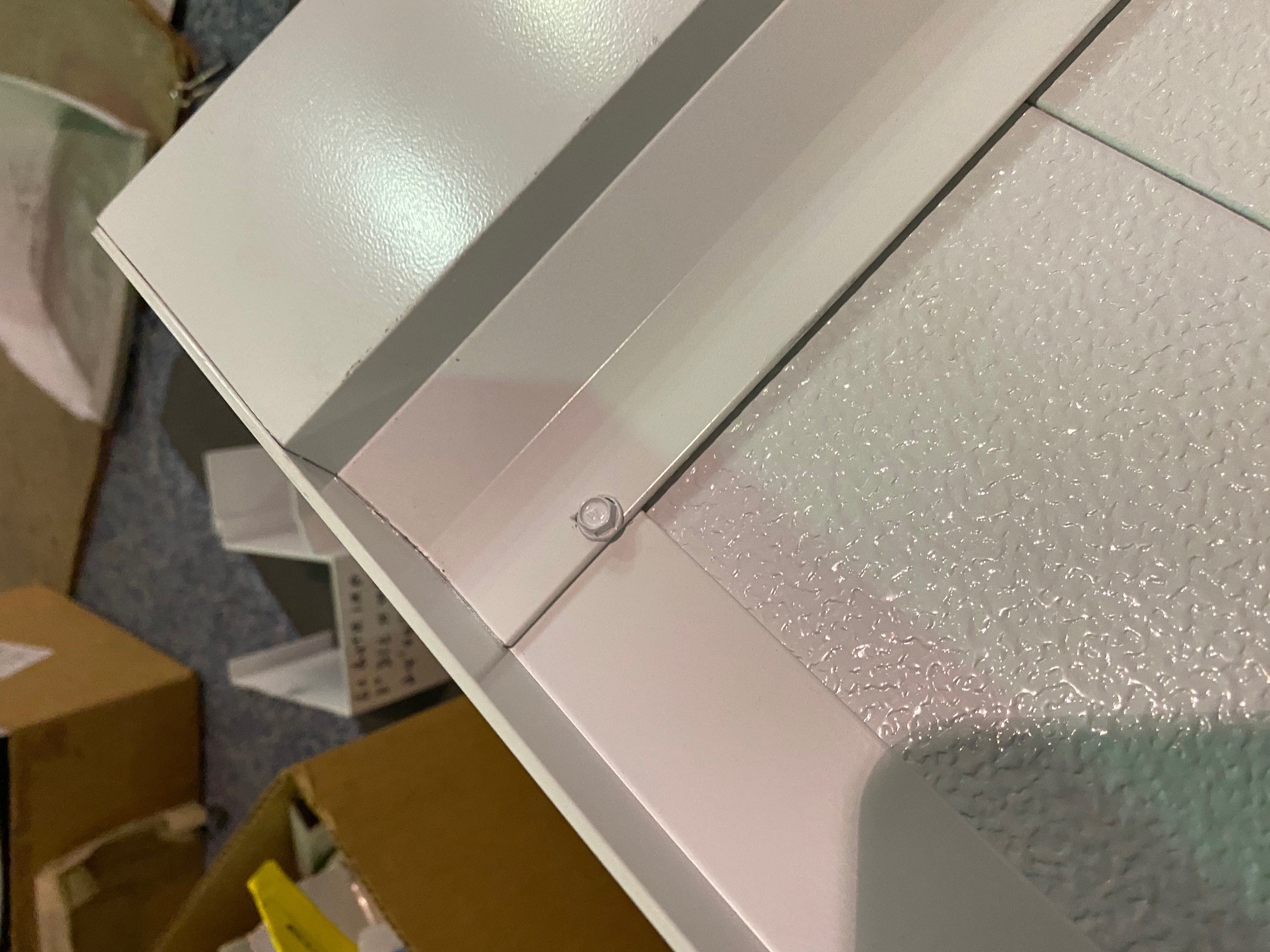
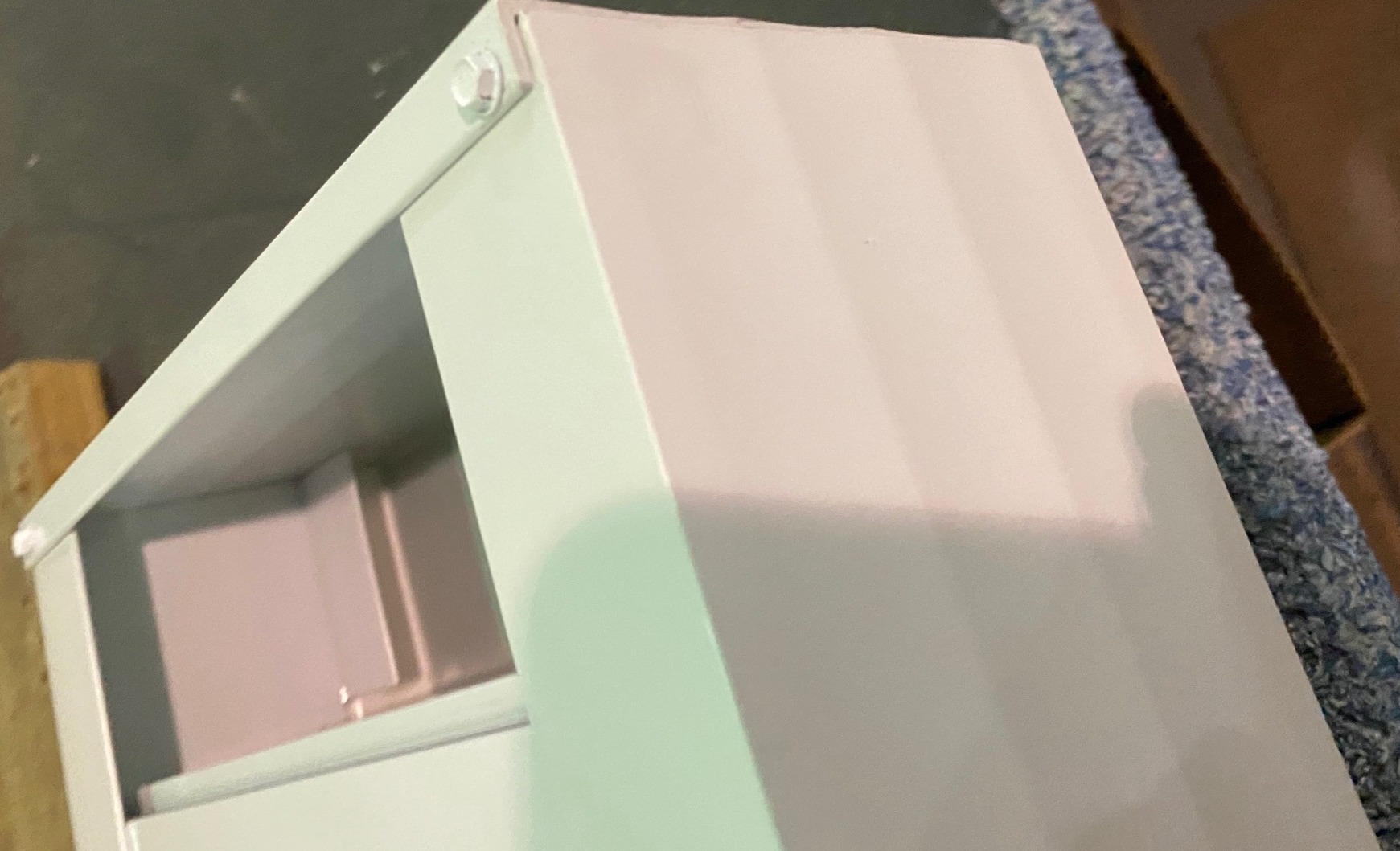
Wipe off any excess caulking. The top leg of the fascia is installed under the front lip of the gutter and then secured with a 3/4" tek screw and then the joint caulked to prevent leaking.
Seal Roof Joints
#White Peel and Seal tar tape is supplied with all orders to finish off each of the seams on the top of your unit. Because the caulking you have applied thus far is likely still setting to some degree, we strongly suggest, before you get up on your roof, that you temporarily support your roof from underneath, at the half way mark of the projection, with padded 2x4 bracing. This will minimize the flexing at the seams as you apply the tar tape. Apply the tape to every seam on the top of your roof. This will include the seams between panels as well as all the seams where the backwall C channel, side fascia and front gutter sit on the roof top.
If not performed in the previous step, put a large bead of caulking on top of each lag screw so as to prevent a water build up in the dimple.
Install Scuppers or Downspouts
#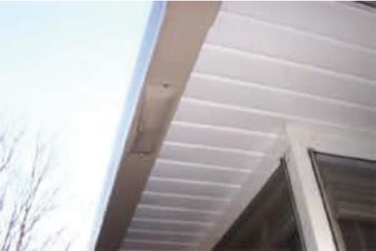
Lastly, due to the design of the panel and the patented snap lock design, it is almost impossible for the panel to leak at the seams. In any patio cover installation, the most critical leak point is where the unit meets the existing structure. We would strongly suggest you use your local supplier to talk about which type of flashing best suits your application. Naturally, if your installation is under an existing soffit, it is already more protected and may not need any additional protective measures.
Prepare to Install Your Screen Walls
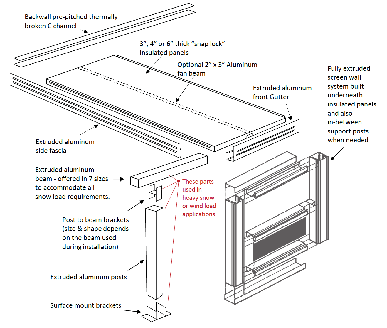
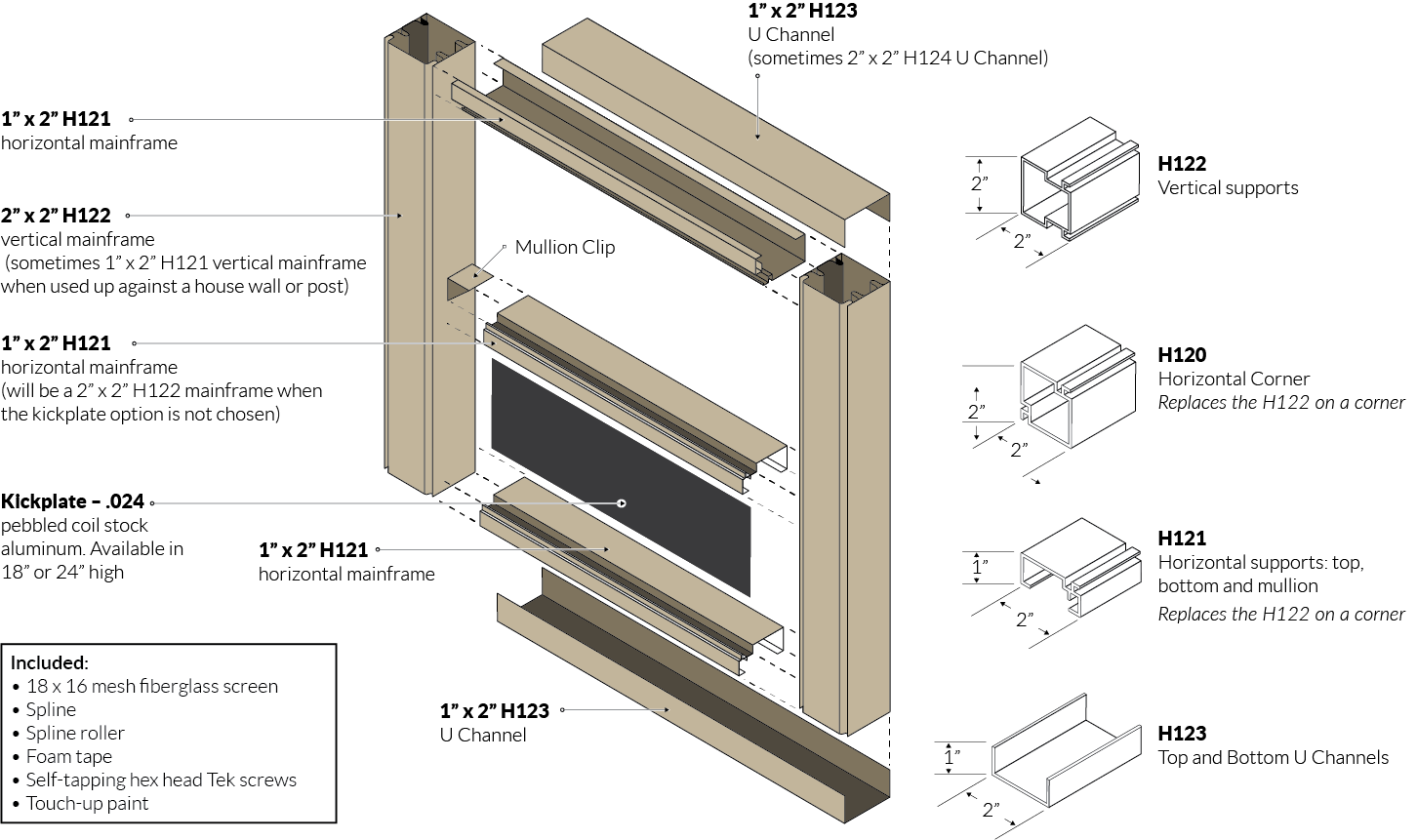
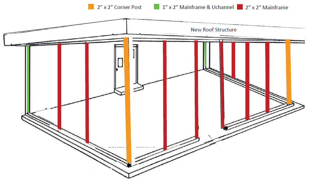
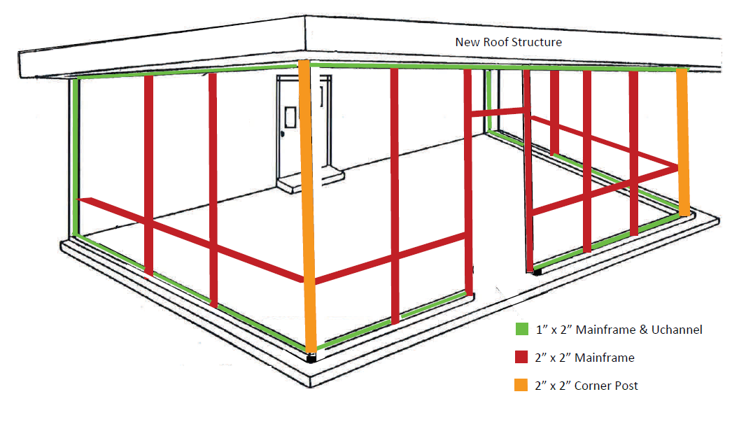
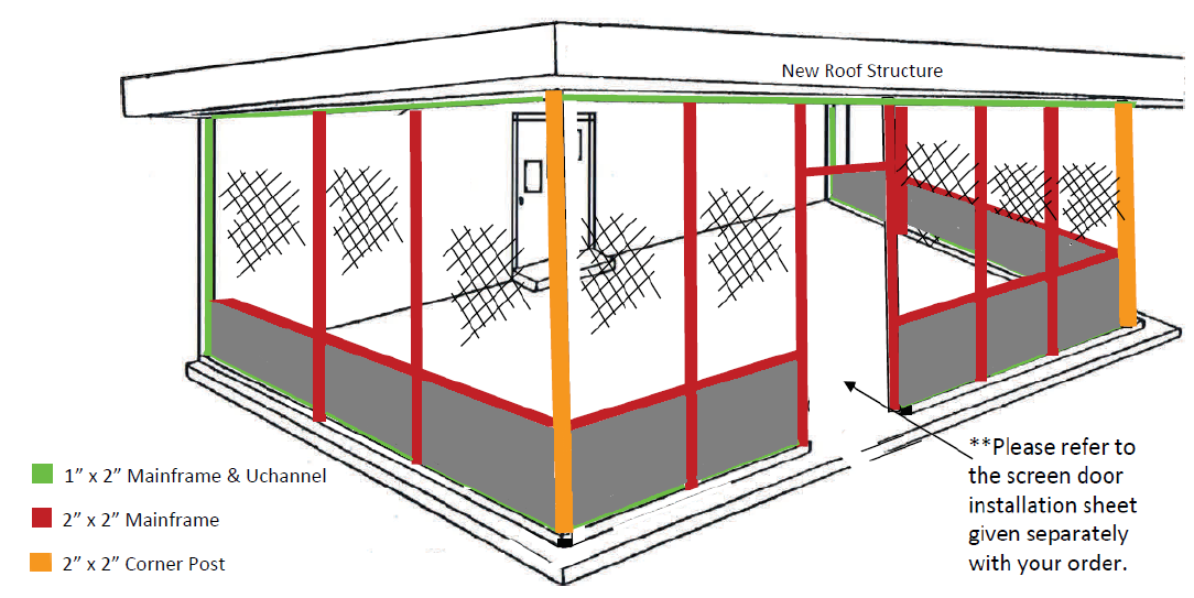
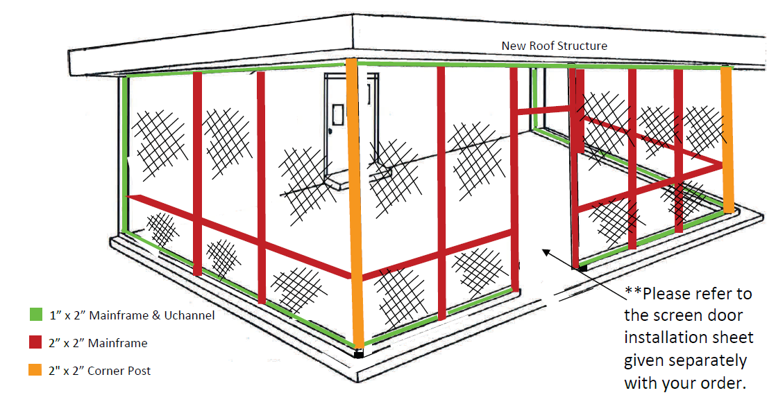
#The remaining pages of this guide outline the installation of your screen walls to complete your new permanent screened enclosure. Familiarize yourself with the basic layout of the room as shown in the blow out image below and layout all the materials ahead of time to ensure you have all the necessary components and quantities to complete the job.
In addition to the details on the following pages, there are a host of valuable resources available in the specific page in our customer portal for the quoted enclosure. You would have received access instructions by email when the order was placed. Please contact as customer service rep if you misplaced these instructions.
Install UChannel
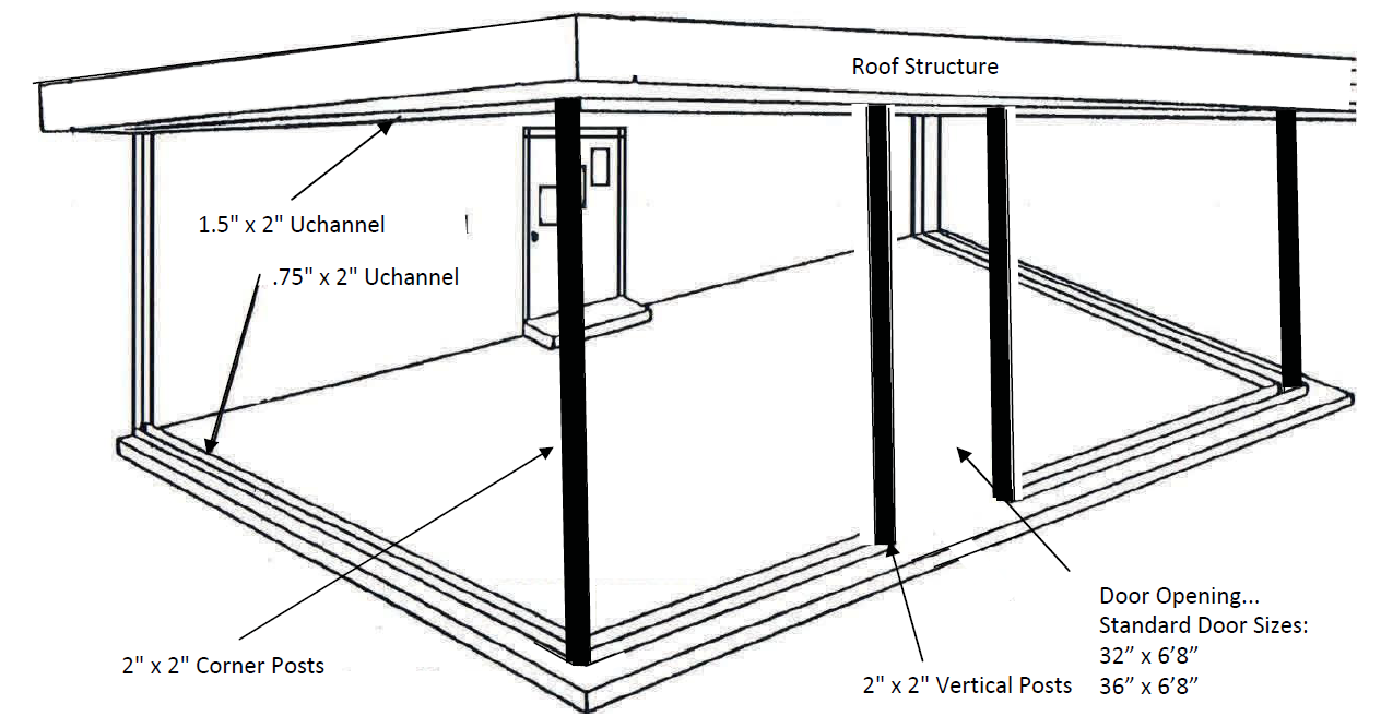
#Uchannel is used to frame in all openings and offer a surface to secure the vertical posts and horiztonal mainframe with spline grooves. It is mounted to the floor, the underside of your existing roofline and all vertically up the house wall on each side of the room. In most cases, we supply .75" x 2" uchannel for vertical and floor installation and deeper 1.5" x 2" uchannel for the underside of the roof line. This will allow for more room to hide the cuts of all vertical mainframe extrusions inside the U channel on this sides and make installation a bit easier.
In your hardware box you will find a roll(s) of 3/4" X 3/4” foam tape. These are supplied You may choose to use this on the back of the vertical U channel installations in the case of an uneven or rough vertical surface, such as brick or step siding. Please note that due to the many different types and styles of house walls, or cement pads or wood decks you will need to supply your own screws/fasteners to attach the HI23 Uchannel to your existing surfaces.
You can choose to miter cut the Uchannels where they meet at the corners; however, the most common, and easiest, choice for installation is a square butt where they meet. For instance, install both top and bottom U channels in one length from house wall to the corner post and then vertical uchannel on house walls gets installed between the top & bottom uchannel installation. For standard outside screened rooms, the horizonal uchannel is run the full width of the front wall on top and bottom as completed in a previous step.
TIP: Uchannel is not run on the floor where a door is to be installed. In such cases, leave a 36" opening between uchannel for a 36" wide door (adjust based on actual door ordered with your kit).
NOTE: If you are unable to screen the room from the outside (existing deck railing interference, for example), your kit will have additional uchannel and 1x2 mainframe to run up the corner posts on both sides to allow you to screen from the inside. If this information wasn't provided during the quote phase, additional material will need to be purchased to complete the inside install.
If you are mounting the Uchannel to concrete or brick, we would suggest using either Tapcon screws or drive anchors to secure the Uchannel to those surfaces. For all wood surface installation you can punch or drill a starter hole in the aluminum and use an appropriate size wood screw to secured the Uchannel.
Though it is not necessary, you can apply a bead of high quality silicone (purchased locally) to the underside of the Uchannel prior to securing it to the cement or wood surface in order to waterproof the seal between Uchannel and floor surface. Alternatively, if you have a sloped pad and you would like to have some drainage, you can drill holes in the uchannel along the length for this purpose. Of course, this does provide an opening for bugs to enter potentially.
We recommend spacing screws or fasteners every 18” to 24” depending on the total length of the installation
Install 1x2 Vertical Mainframe
#Now that uchannels are installed, its time to install all the vertical members and secure to this uchannel. Refer back to your custom layout drawing and identify all verticals that will be installed to complete your room.
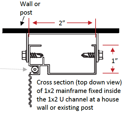
To start, cut and Install the 1" X 2" mainframe in the Uchannel previously installed on the house wall. You will use the Uchannel as means of plumbing this mainframe. Secure the 1x2 mainframe into the U channel using the supplied self tapping hex head Tek screws. Secure the mainframe with the Tek screws on both sides at a rate of (4) Tek screws per 8 ft. length on each side.
NOTE: Be sure not to place 1x2 mainframe all the way down into the Uchannel as you must leave the spline groove exposed for screening, as illustrated on the right.
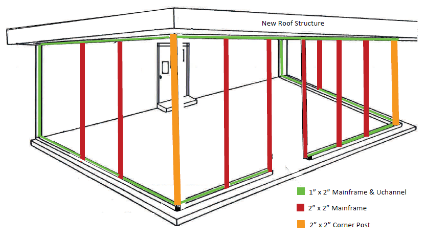
Generally, 1x2 mainframe will be used up existing vertical house walls (illustrated below in the ‘green lines'; however, 2x2 mainframe can be used as well. It would be provided when a door is installed adjacent to the house wall (or on request) and would attached the same way as the 1x2 mainframe. Consult the drawings for your custom room to confirm which profile of mainframe is to be used against existing surfaces in your application.
Install 2x2 Mainframe
#Next install the 2" X 2" vertical mainframes. You will space them apart based on the spacing indicated in the drawing that came with your quotation prior to making your purchase.
NOTE: Spacing indicated in your drawing is post / house wall to centerline of 2” vertical and centerline of vertical to vertical. You do not have to worry about being precise with this cut (length of vertical) since any small indiscretion will be hidden inside the top and bottom U channel. Additionally the spacing between verticals is flexible ( 1/2” to 1”) as long as you do not exceed the width (.1”) of the screening provided
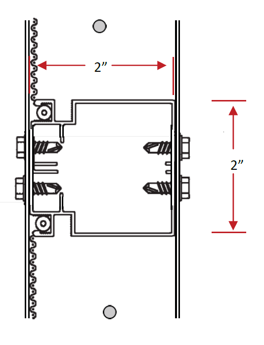
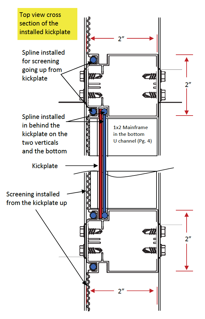
Secure the 2x2 mainframe in place, inside the top and bottom U channel, by using the self tapping hex head Tek screws. Secure both top and bottom and on both sides as illustrated on the right in the overhead cross section of a 2x2.
Finally, install 2” x 2” mainframes on either side of door opening, making sure they are plumb and have enough space between to accommodate the door to be installed. For example, if you have a 36” door you will need a daylight opening between verticals of exactly 36" wide x 80" high. Install a 2” x 2” on either side, leaving exactly 36” for your door installation. Once again, refer to your drawing that came with your quotation, prior to purchase, to be sure of what you need to do for your application.
Tip
- If you plan on putting your door in the first section against the house wall, or on a post the 2" X 2" will be used instead of 1" X 2" in the wall uchannel. This will be accounted for in your materials we have supplied.
- There is no bottom U channel nor 1” x 2” mainframe in door openings.
2x2 Enclosure with Verticals Installed
Install Horizontal Mainframes
#Depending on opening sizes and options select for your room during the quotation stage, there will be several different configurations, each with a slightly different final installation approach. Every installation will need to follow step 9A, but 9B and 9C will only be needed if you have chair rail and/or kickplate, respectively. Rooms with both a chair rail and a kickplate should follow all steps 9A through 9C.
Install Mainframe in Uchannel
#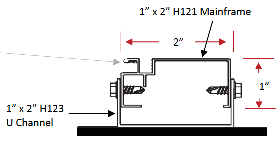
If you do not have a chair rail, install 1 "X 2" mainframe as the door header, 80" from floor. If your unit will have a chair rail and or has a kickplate that uses a 2x2 mainframe over the top, install 2" X 2" as the door header. Again, the opening will need to be 80" from the floor to the underside of the door header.
For rooms with multiple chair rails, repeat the step above in each opening with the other chair rail(s).
Install Chair Rail
#Rooms with openings larger than 42" and without a kickplate are recommended to have a chair rail for strength. The material used for the chair rail is the same 2x2 mainframe used for the vertical members.
Cut and install the 2" X 2" mainframe to fit between vertical mainframe you have installed in a previous step. You may install the horizontal chair rail at any height you wish unless local building code has a specific requirement. Otherwise, we would recommend sitting in your favorite outdoor chair, and install the 2” x 2” horizontal at a height that does not interfere with your sightline into your backyard.
Install Kickplate (where applicable)
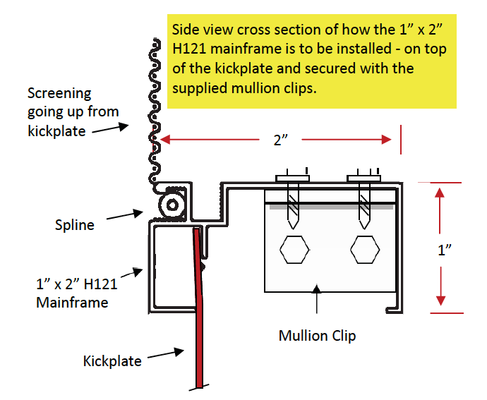
#In general, kickplate is installed with 1x2 mainframe securing the kickplate which is shown in this section. For rooms that have openings greater than 54", 2x2 mainframe would be provided and would follow the same general process.
Measure openings then cut and install the 1x 2 to fit between vertical framing members right above the kickplate.
Temporarily set 1x2 mainframe over kickplate and make sure the kickplate slides completely into the designed groove (see the first illustration on the right).
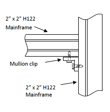
Once it is firmly seated, take a mullion clip and slide it up under the 1x2 mainframe where it meets each vertical framing member. With a pen, lightly mark the 2" X 2" vertical framing member where the clip ends with a line. Then remove the 1x2 mainframe and screw the mullion clips (one per side) to the vertical framing members using your mark as a guide for the bottom of the clip. As another reference, the top of the clip should be about 1/4” above the top of the kickplate.
To accommodate the slope of the ceiling , floor or both, you must keep the top of the kick plates even from one opening to the next. You can use a string, running the full width of the opening, to accomplish this.
The bottom of each kickplate section can be trimmed according to the slope of your application.
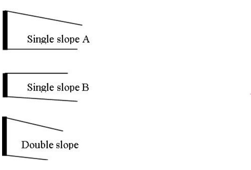
Still using the ‘single slope B’ example above, if you install the 1x2 mainframe on top of the kickplate to run parallel to your roof line, your kickplate will get slightly larger on the “outside” vertical measurement, as you move away from the house wall to the front of your installation. The alternative is to run the kickplate perfectly parallel to the mounting surface (deck or patio) and the top screen section “outside” vertical measurement, will increase slightly as you move away from the house wall to the front of your installation.
Place the 1x2 mainframe on the mullion clips you have just installed and screw down (from the top of the H121) into the clips with the supplied self tapping hex head Tek screws.
NOTE: In cases where a room is ordered with double height kickplate, the above process is performed a 2nd time. to achieve the full height.
Install Screening
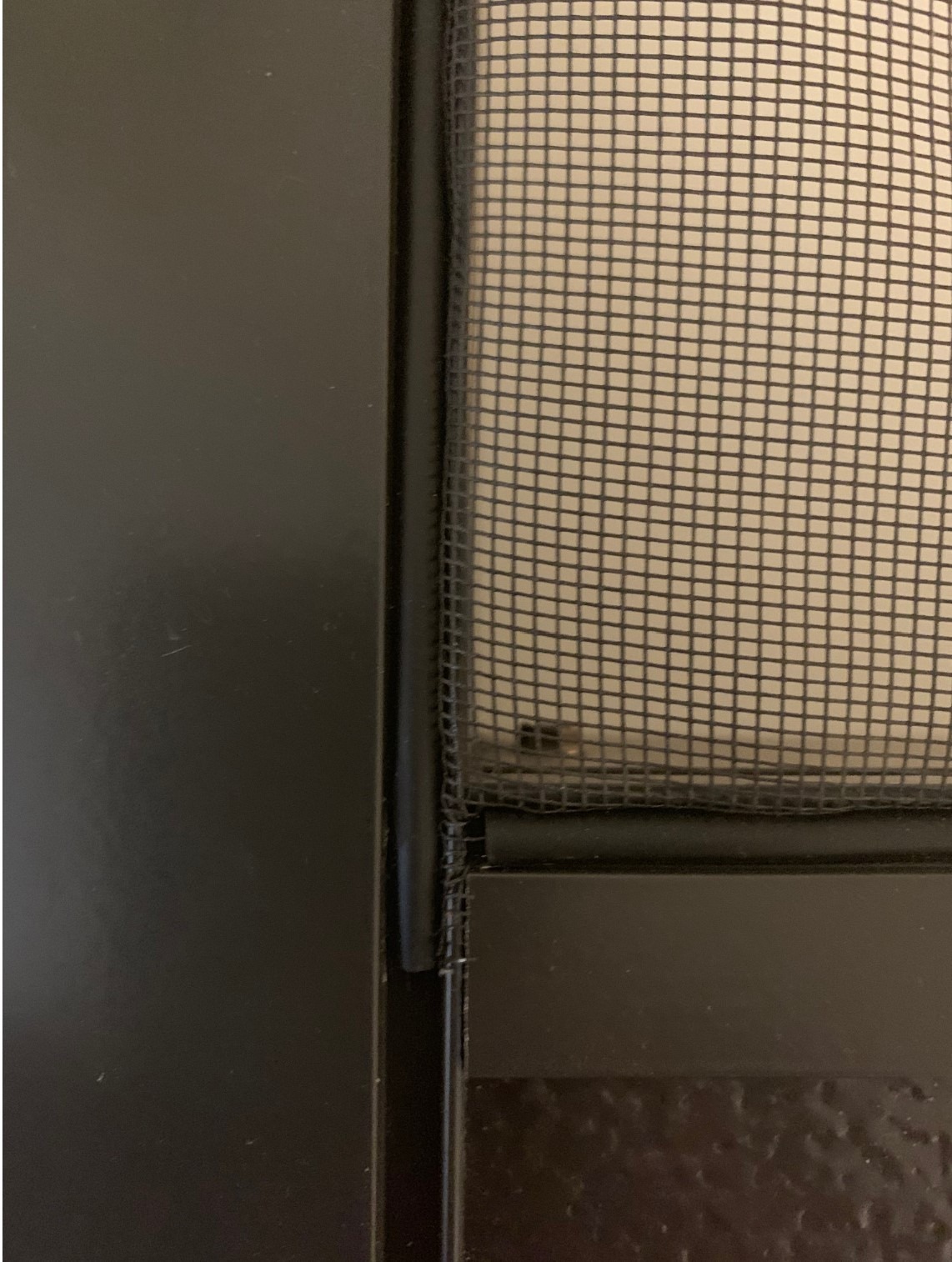
#Using the supplied screen, spline and spline roller, you will be screening in all openings generated through the construction of the room. If all steps above were complete properly, all openings show have spline grooves visible around the perimeter of the opening. If any opening is missing a spine groove, please review the appropriate section of the manual to correct.
If your room has no chair rail or just a kickplate, there will just be one opening per section to screen. For rooms with a chair rail, there will be a section below and another above the chair rail to screen in. The small opening above the door is also to be screened in.
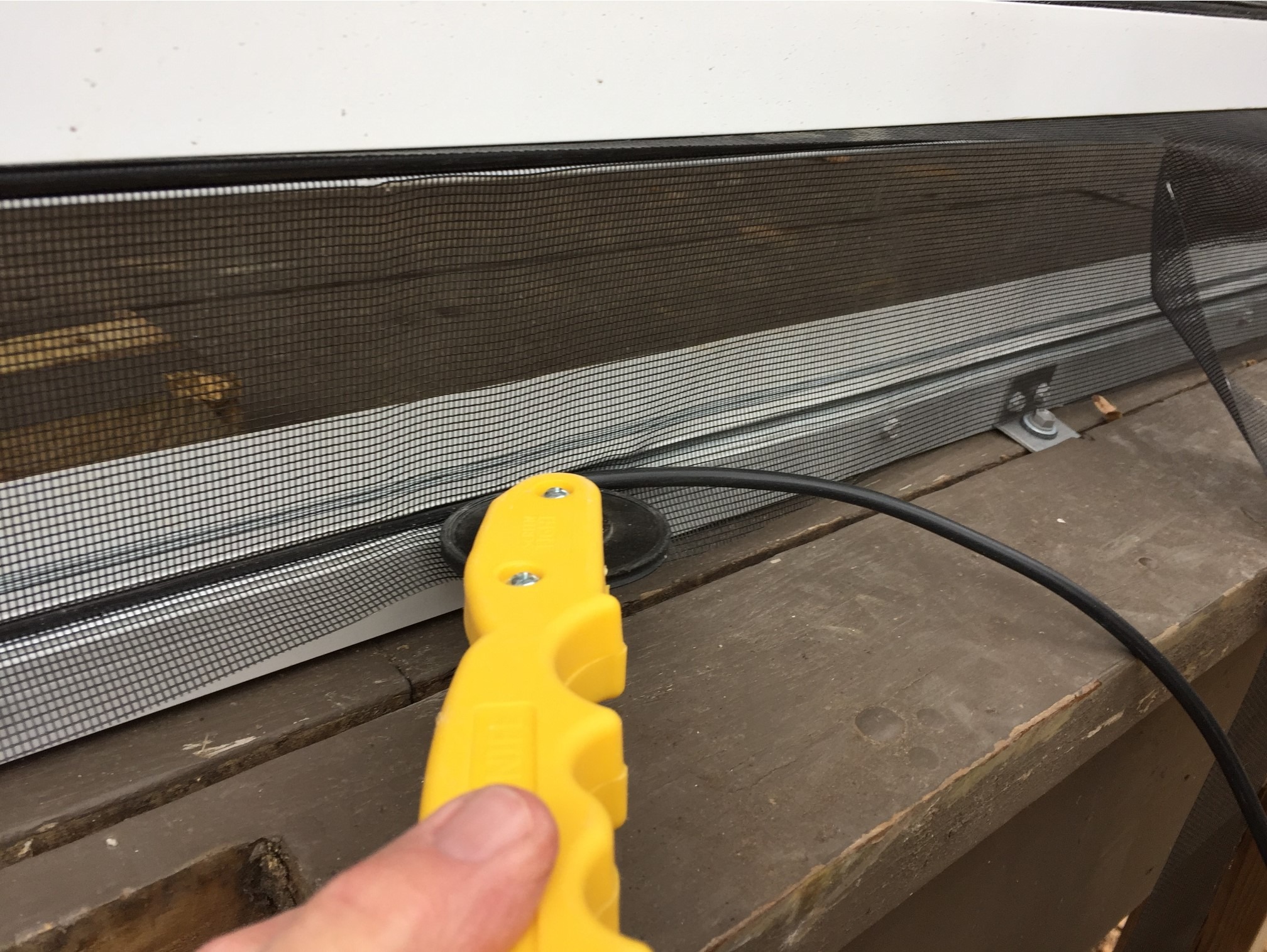
We suggest rolling the spline and screening into the vertical spline grooves first, where the most tension on the screen will be at the midpoint of the vertical installation. Once you have both sides started you can have someone apply a light inward pressure with their hand on the screen as your roll the spline in. You can also try dragging the tip of your fore finger on the screening out in front of your spline as you roll to prevent the spline from pulling the material too tight.
**You will need to take extra care not to pull the screen too tight on the up & down dimension. You may warp the horizontal center bar off ‘straight.’
TIPS:
- If installing in cooler temperatures (below 50 degrees F), the spline may be more rigid and difficult to install. You can warm the spline to make it more malleable using a hair dryer or by putting the spline roll inside your jacket and run it out the arm as you install.
- For large openings or if you experience difficulty holding the spline in place, there are spline clips available here that make installation a little easier.
CONGRATULATIONS!
You just saved thousands of dollars on a professional grade room. We hope you enjoy many years of maintenance free protection from bugs and the elements. If you have questions or need support at any time, please call us toll free at 1.800.922.4760.