3" Screened In Porch Systems
Installation manual for the 2x3 screened in porch kits with existing cover in place.
Thank You for Purchasing a ScreenHouse DIY Porch and Patio Screen Wall Kit #
Your kit has been designed and engineered with over 20 years of experience in both commercial and residential design. It is proudly manufactured in the USA using responsibly sourced materials in state-of-the-art facilities at Superior Mason and Four Seasons Building Products.
This product is backed by one of the best warranties in the industry:
Insulated panels: Limited 15-year warranty
Aluminum extrusions: Limited lifetime warranty
Disclaimer
#This guide is provided as an installation reference only. Because every existing structure is different, it is not possible to cover every scenario. Fortunately, your kit is designed to be highly adaptable, and most errors can be corrected with the materials supplied.
Installation requires patience and common sense. If you are uncertain about any step, please contact us by phone or email for support. Additional resources—such as a reference cut sheet, 3D model, and drawings (plan view, roof view, elevation view, etc.)—are available in your customer portal or upon request.
Important: We are not responsible for errors in cuts made to the material.
Please Read Before You Begin
#Review the entire installation guide step by step before starting.
We recommend 1–3 physically fit individuals with basic DIY experience. With proper planning, installation can typically be completed in 1–2 days, depending on room size.
Understand each task before beginning, and ensure all required tools are available. Some components may need to be altered to suit your specific structure.
This guide is intended to be used alongside the custom layout provided with your quote.
Note: There are multiple configurations and installation methods. This guide covers a 2x3 screen wall system for a walls-only installation with an existing roof in place.
If your quote specifies a 2" wall system or a full enclosure with roof, please refer to the correct installation manual.
Safety First: Inspect your work area before beginning. Identify all electrical lines, outlets, and other hazards. Do not begin installation until the project area is completely safe.
Tools Required
#Tools are not included with your kit but are necessary for successful installation. Each structure and location is unique, so review your custom layout and contact us with any questions at 1-800-922-4760.
Tools
- 1–2 helpers
- 4 ft. carpenter’s level
- Carpenter’s square
- Chalk line (to mark U-channel locations)
- Cordless drill/nut driver
- Caulking gun
- Chop saw with metal-cutting blade (required for precise cuts)
- Ladders
- Masonry drill bits and fasteners (for concrete installation, if needed)
- Metal file (to smooth cut edges)
- Hammer, screwdrivers, drill, tape measure, utility knife
- Gloves and safety eyewear
Materials
#Before beginning, inventory all materials in a safe staging area. Each step of this guide will reference the specific components needed. Because each room is custom, not all items listed will be included in every order. A room-specific materials list and cut sheet are available in your customer portal or upon request.
Notes:
Materials
- While we strive to keep this guide current, individual components may occasionally be replaced with equivalent versions at the manufacturer’s discretion. If you have questions about substitutions, contact our support team for guidance.
- A “*” in the part number indicates a color designation.
- Items labeled as “Special Car Wash” or “Custom Walk Cover” on your Bill of Lading are generic catch-all terms used by the manufacturer. These are not additional materials—only shipping labels for the bundled items listed afterward.
| Diagram | Part Number | Part Description | Dimension |
|---|---|---|---|
|
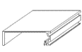
05263* | 0.68" x 3" Uchannel | .75" H x 3" W x 24' L |
|
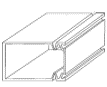
05268* | 1" x 3" mainframe | 1" H x 3" W x & 24' L |
|
05271* | 2" x 3" mainframe | 2" H x 3" W x 24' L |

|
052734* | 3" x 3" Outside corner post (Standard) | 3" H x 3" W x 24' L |

|
052595* | 1.5" x 3" uchannel | 1.5" H x 3" W x 24' L |
|
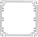
052647* | 3" x 3" Multi-Corner (Spline grooves at 4 corners, no kickplate groove) | 3" H x 3" W x 24' L |
Screen Wall Components
| Diagram | Part Number | Part Description | Dimension |
|---|---|---|---|

|
11011* | 2" Mullion Clips (supplied on orders with a kickplate) | 1" x 1" x 2" |
|
|
11014* | 3" Mullion Clips | 1" x 1" x 3" |
|
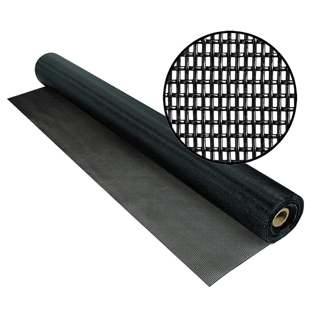
Varies by type | Screen roll | Width varies, 100' long |
|
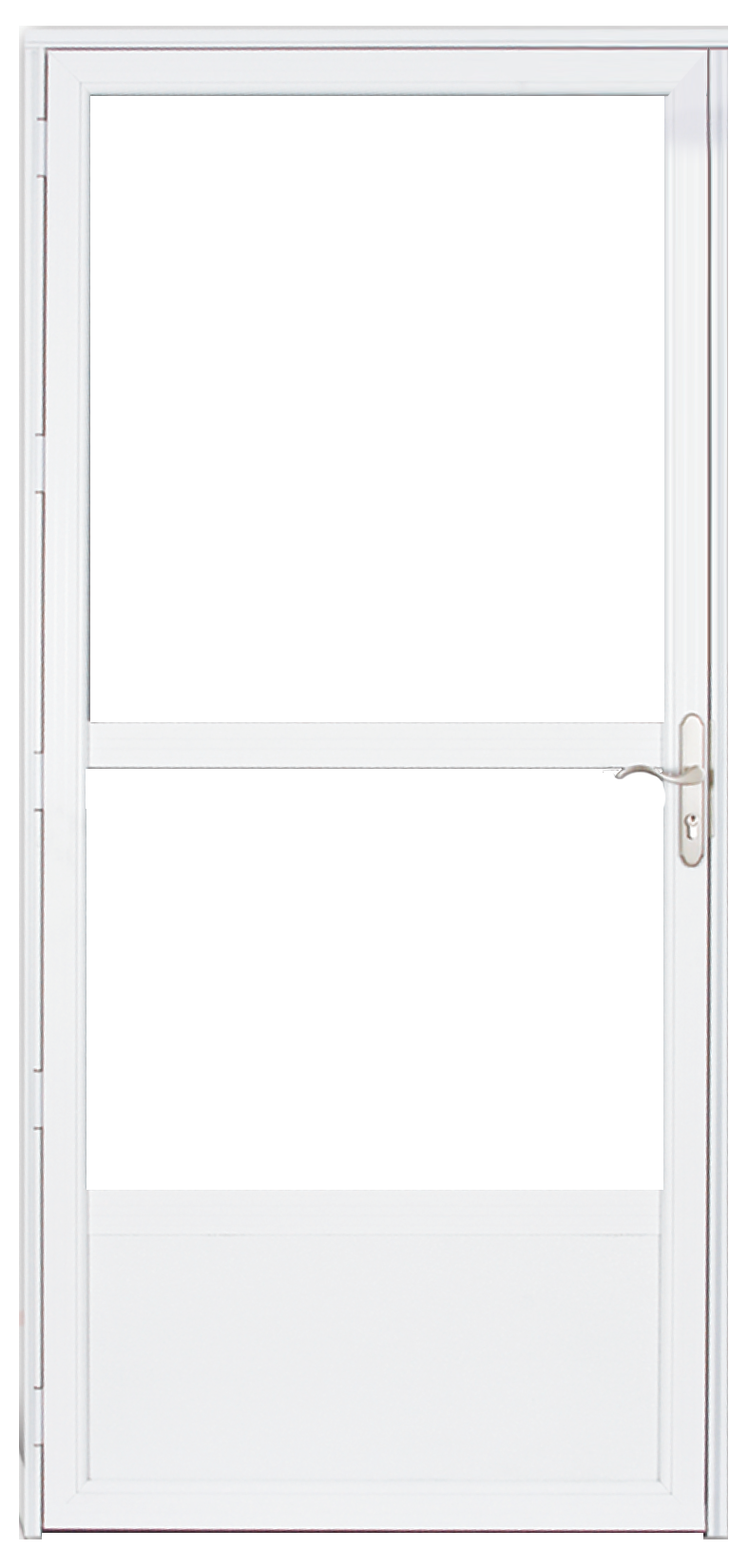
25* | Series 2600 Screen Door (assembled or knockdown) | 36" or 32" W x 80" W (standard) |
|
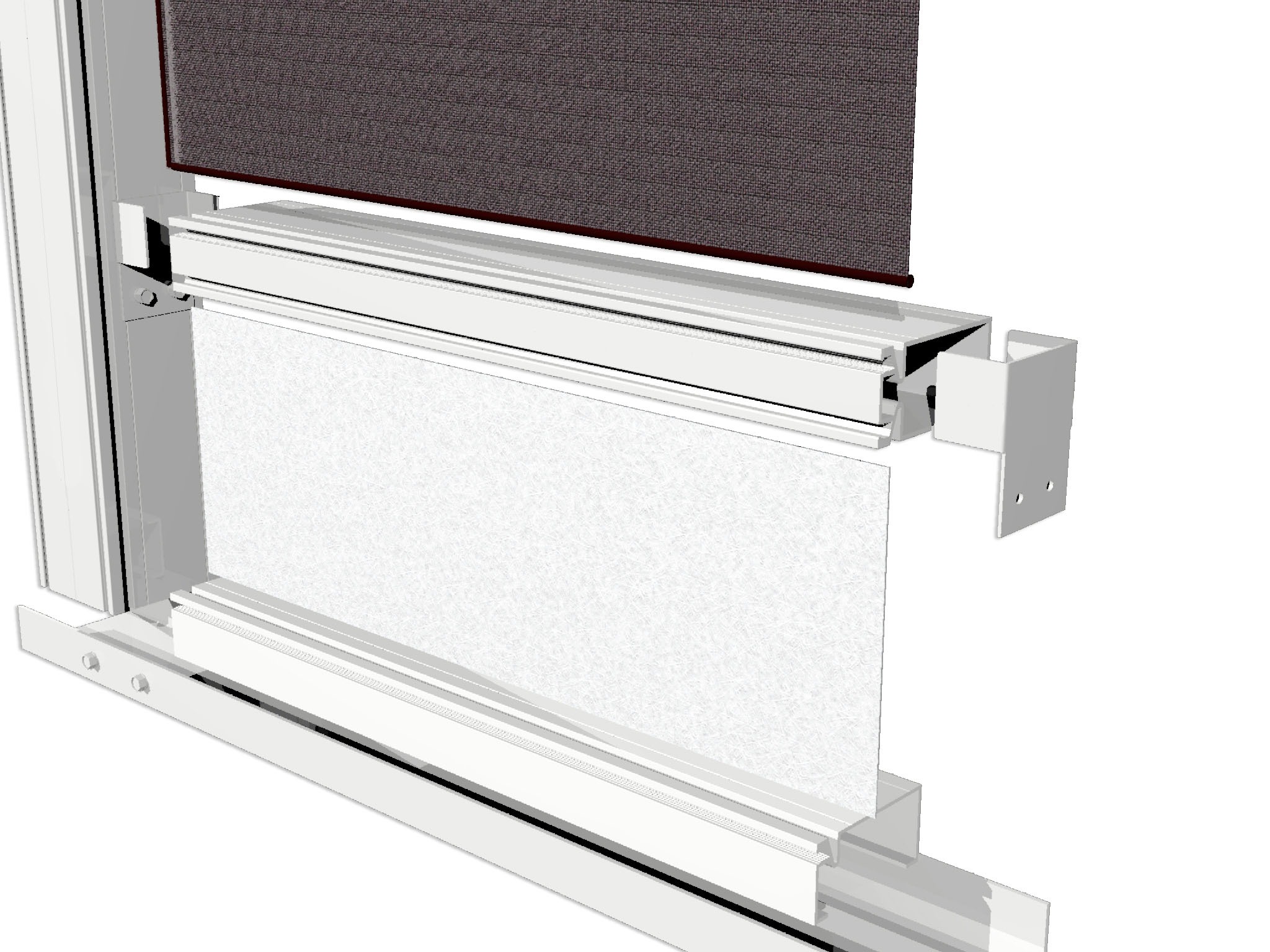
F250K* (18")047475* (24") | Embossed Kickplate - 50' roll in most cases in an individual box | 18"H x 50'L24"H x 50'L |
|
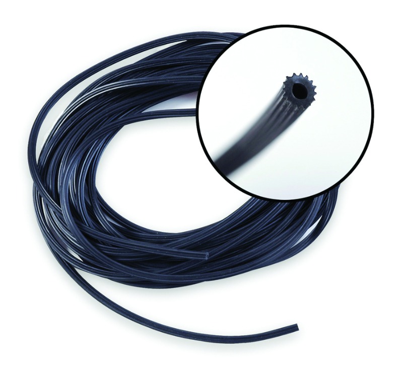
124-F | Flat Spline | .180" x 1500' |
|
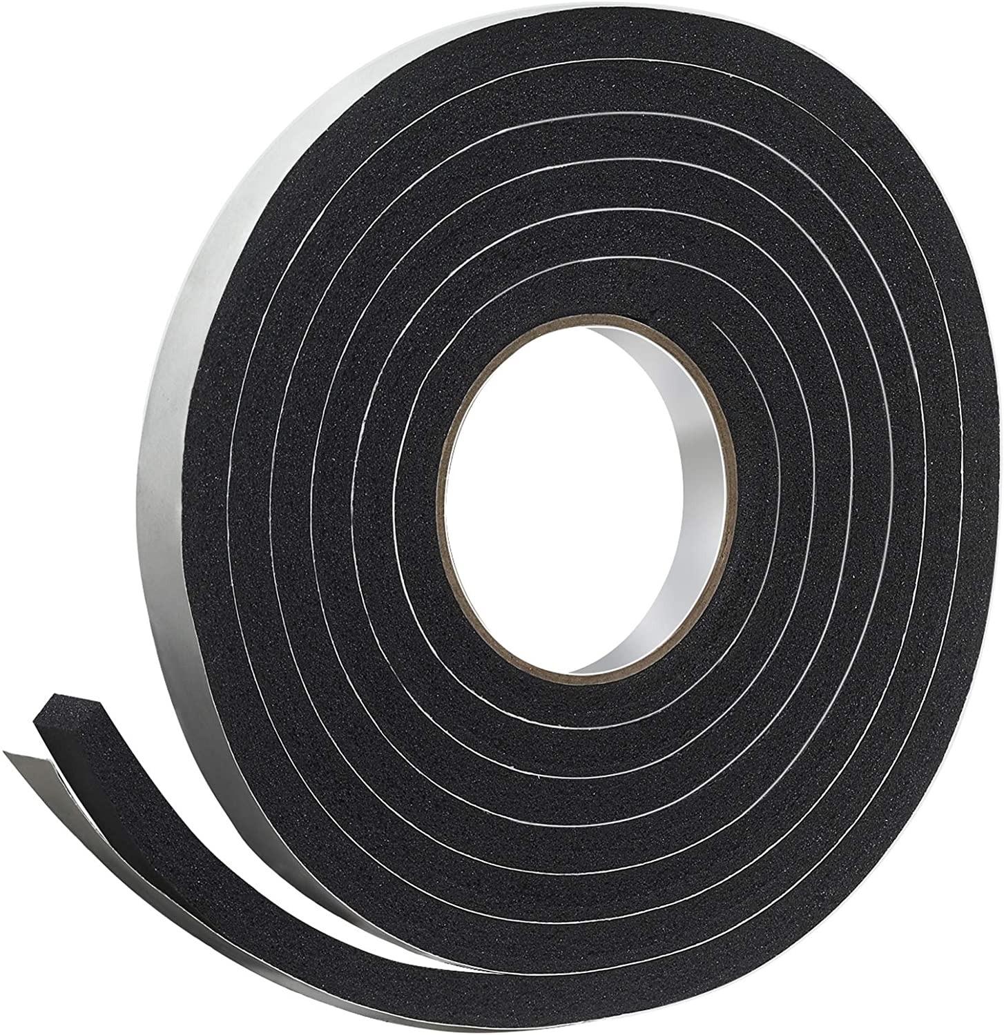
H310A0015 | Foam Tape | 1/2" W x 15' L |

|
P860* | Touch up paint | NA |
|
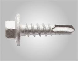
819536* | Color matched tek screw | #8 x 3/4" (100 per pack) |
|
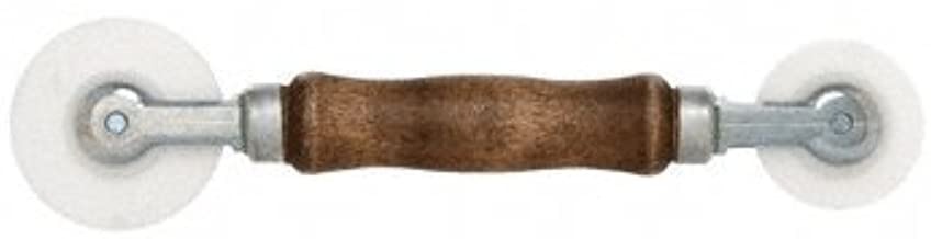
T410 | Heavy Duty Screen Roller | NA |
Screen Wall Kit Overview #
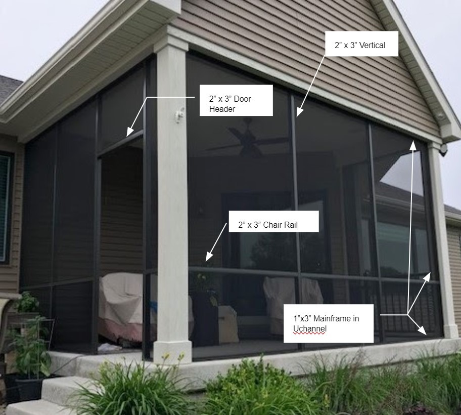
Additional Resources
Along with the instructions in this manual, you’ll find a variety of helpful resources in your customer portal, specific to your quoted enclosure. Access details were emailed to you when your order was placed.
If you no longer have these instructions, please contact a customer service representative for assistance.
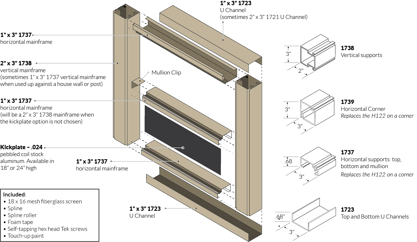
3" Screen Wall System Exploded Detail
Step 1: Install U-Channel
Between the guidelines below and the drawing included with your quotation, you should have everything needed to assemble your unit. If you need clarification at any point, we are always happy to help.
Before cutting any material:
Lay out all the pieces supplied.
Review how each piece will be cut and placed.
Confirm you have enough material to complete the job.
If in doubt, call us before cutting.
Note: To keep pricing as reasonable as possible, we make efficient use of standard extrusion lengths (16' and 20'). In some cases, this requires butt splicing certain profiles, most commonly on the top, bottom, and rear wall U-channels.
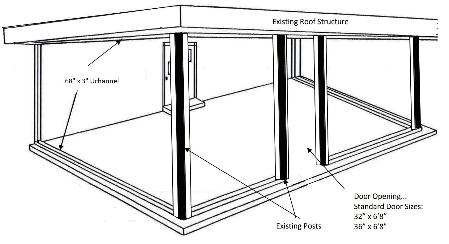
Purpose of U-Channel
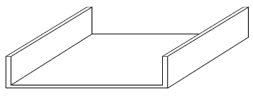
U-channel frames each opening and provides a surface for securing vertical posts and horizontal mainframes with spline grooves. It is installed:
On the floor
On the underside of your existing roofline
Vertically up the house wall on each side of the room
On any existing posts
Tip: Do not install U-channel across the floor where a door will be located. Leave a 36" opening (or adjust for your actual door size).
Cutting and Installation
You may choose to miter cut U-channels where they meet at corners.
The most common and easiest method is a square butt joint:
Run the top and bottom U-channels in one continuous length from the house wall to the corner post.
Then install the vertical U-channel between the top and bottom.
For standard outside screened openings:
Install horizontal U-channel the full width across the top and bottom.
Cut vertical U-channel to fit between them.
Foam Tape for Uneven Surfaces
In your hardware box, you will find ¾" x ¾" foam tape. Apply this behind vertical U-channels if installing against uneven or rough surfaces such as brick or step siding.
Other Installation Tips
Concrete or Brick: Use Tapcon screws or drive anchors to secure the U-channel.
Wood or Trex Decking: Drill a starter hole in the aluminum and use galvanized or zinc-coated deck screws. (Mounting hardware is not included in your kit.)
Waterproofing (optional): Apply a bead of high-quality silicone under the U-channel before securing it to the cement or wood surface.
Drainage (optional): Drill holes along the length of the U-channel if you prefer water drainage. Keep in mind this may allow insects to enter.
Step 2: Install 1" x 3" Vertical Mainframe
With the U-channels installed, begin placing and securing the 1" x 3" vertical mainframes. Refer to your custom layout drawing to locate each vertical member and confirm its position.
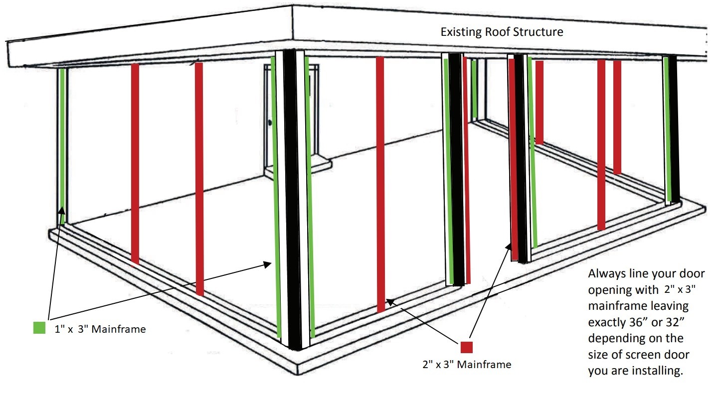
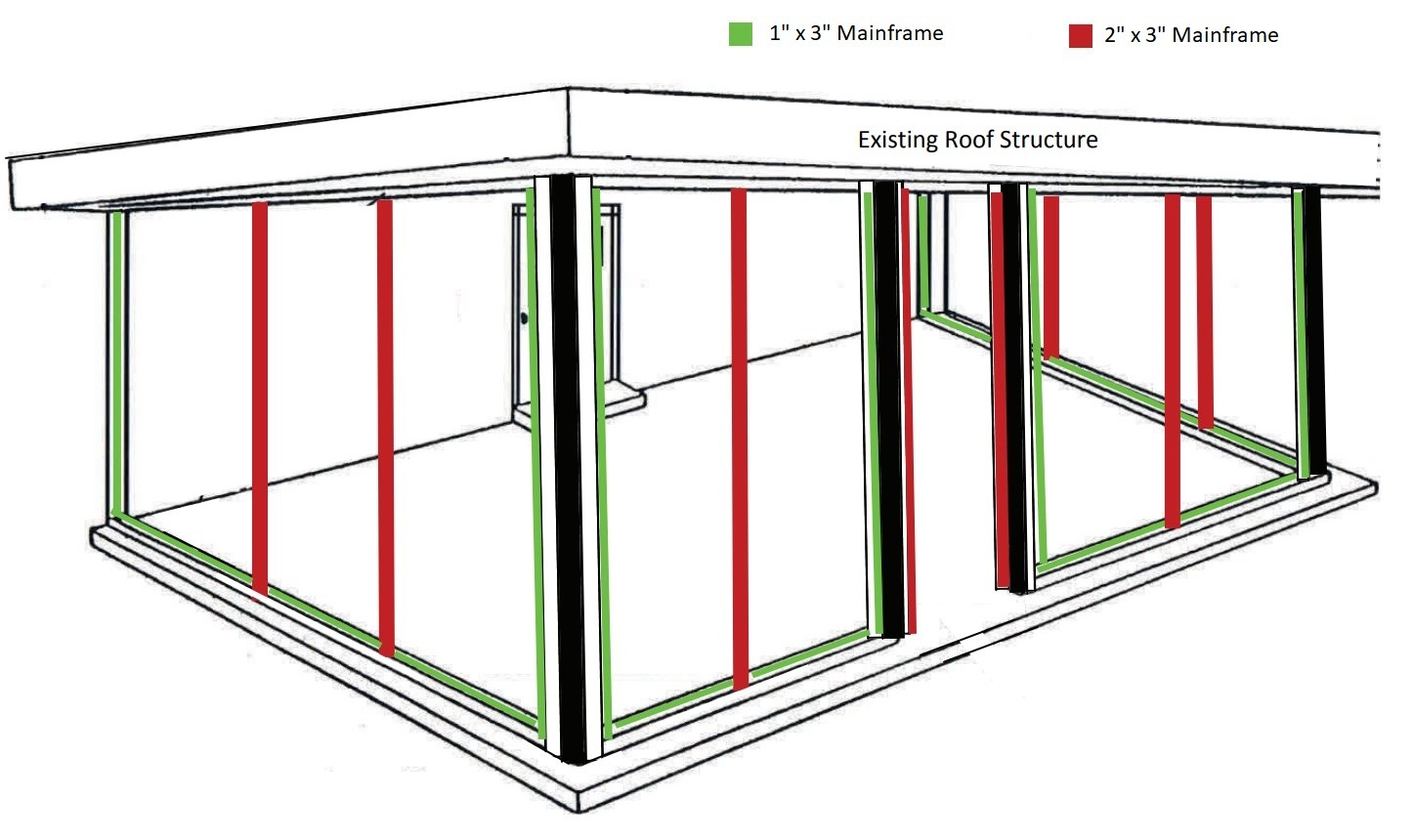
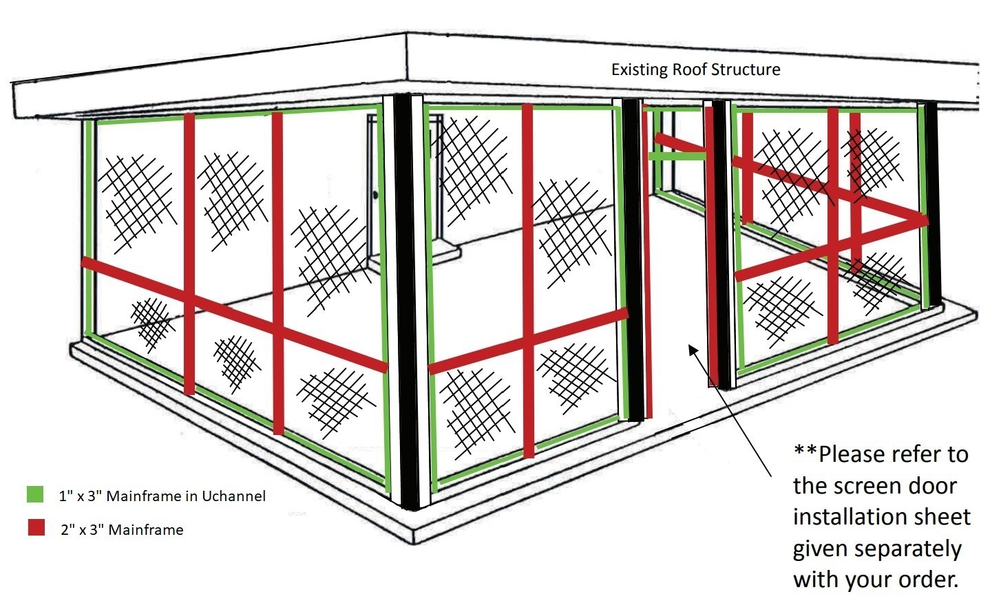
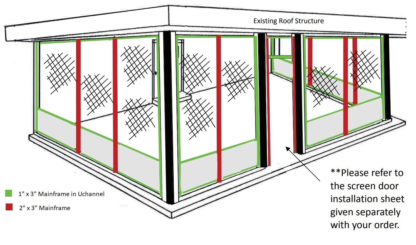
Tip: In your layout sketch, vertical members are shown in green for easy reference.
Installing the 1" x 3" Mainframe in the U-Channel
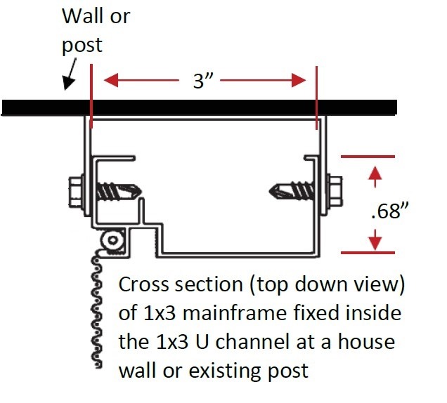
Cut and install the 1" x 3" mainframe into the U-channel previously installed on the house wall and along all existing posts.
Use the U-channel to ensure the mainframe is properly plumb.
Secure the 1x3 mainframe into the U-channel with the supplied self-tapping hex head Tek screws. Fasten both sides at a rate of 4 screws per 8 ft. length.
Note:
When using a 1.5" x 3" U-channel, do not seat the 1x3 mainframe all the way to the bottom. The spline groove must remain exposed for screening (see illustration on the right).
With the standard .068 x 3" U-channel, this is not an issue—the 1x3 mainframe can sit fully at the bottom of the channel.
Mainframe Against Existing Walls or Posts
In most cases, a 1" x 3" mainframe will be used against existing vertical house walls and posts (shown as green lines in Step 3).
A 2" x 3" mainframe may also be supplied in the following situations:
When a door is installed next to the house wall
Or if specifically requested
The 2x3 installs the same way as the 1x3. Always refer to your custom room drawings to confirm which mainframe profile should be used against existing surfaces in your application.
Step 3: Install Vertical 2" x 3" Mainframes
Install the 2" x 3" vertical mainframes as shown in your custom room layout sketch:
Red indicators = vertical mainframes
Yellow indicators = corner posts
Space the verticals according to the measurements in the drawing provided with your quotation.
Make sure to orient the spline grooves correctly for your application:
Outside screening is the most common approach.
Inside screening is acceptable if the outside of the wall is not accessible.
Note:
Spacing in your drawing is measured from the post/house wall to the centerline of the 2" vertical, and from centerline to centerline of each vertical.
Precise length cuts are not critical—minor variations will be hidden inside the top and bottom U-channels.
Spacing between verticals can vary by ½" to 1", provided you do not exceed the maximum screen width tolerance of ±0.1".
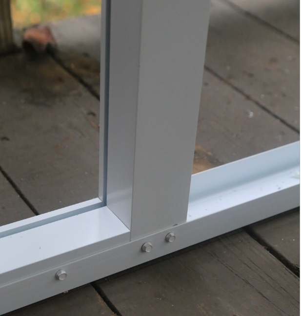
Installing 2x2 Verticals (Outside Screen Application)
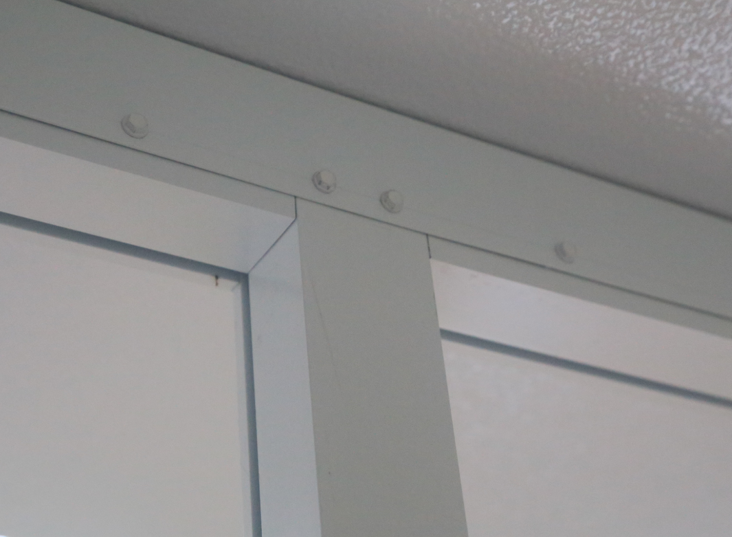
The images below illustrate the correct installation of 2x2 verticals for an outside screen application. The same method applies to the 3" wall system, with the only difference being the added depth.
Always ensure that the kickplate grooves on the inside face of both the vertical and horizontal mainframes align, as shown.
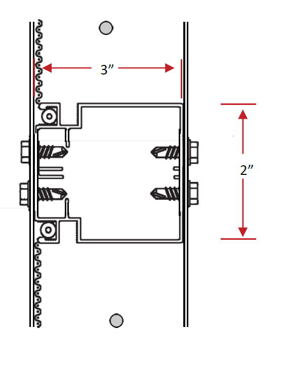
Installing 2x2 Verticals (Outside Screen Application)
The images below show the correct installation of the 2x2 verticals for an outside screen application. The process is identical for the 3" wall system, with the only difference being the added depth.
The kickplate grooves on the inside face of both the vertical and horizontal mainframes should always align as shown.
Tip
If you plan to install your door in the first section against the house wall, or on a post, a 2" x 3" mainframe will be used in the wall U-channel instead of a 1" x 3". This adjustment is already accounted for in the materials supplied with your kit.
Door openings do not require a bottom U-channel or a 1" x 3" mainframe.
Step 3A: Install Corner Posts (Optional)
Some installations will not use existing posts (for example, when working inside or outside of railings). If this does not apply to your room, skip this step and continue to the next one.
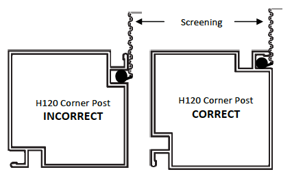
For these applications, we provide 3" x 3" corner posts to allow screening where two walls meet at a 90-degree angle. When installing, take care to orient the posts correctly—if a post is installed upside down, the screen and spline will not seat properly, and the screen may pop out easily.
Installing Corner Posts in the U-Channel
When setting the corners into the U-channel, make sure the spline groove is positioned correctly for screening each wall and not mistaken for the kickplate groove.
The screen spline grooves should face outward on both the front wall and the side wall.
When oriented properly, the kickplate grooves will be on the inside face of the corner post in each direction (inside the U-channel).
Install Horizontal Mainframes
#The exact configuration of your horizontal mainframes will depend on the opening sizes and options selected for your room during the quotation stage. Each installation will follow a slightly different approach:
Step 4A (required for all rooms): Install the 1" x 3" mainframe in the U-channel.
Step 4B (if applicable): Install a chair rail.
Step 4C (if applicable): Install a kickplate.
Rooms with both a chair rail and a kickplate should complete all steps 4A through 4C.
Installing the 1" x 3" Mainframes
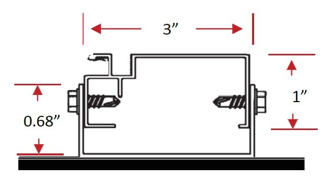
Cut the 1" x 3" mainframes to fit between the vertical framing members.
Install them into the floor and roof channels using the self-tapping hex head screws provided.
Position each mainframe so the spline groove remains exposed, then fasten securely with the screws.
Note: If your openings are not perfectly square (for example, due to the roof slope), you can adjust by lifting one side of the mainframe slightly out of the U-channel. This will help square off the opening and is especially useful if you plan to add 2-season windows in the future.
Installing the Door Header
If your room does not include a chair rail, install a 1" x 3" mainframe as the door header at 80" from the floor.
If your unit has a chair rail and/or a kickplate with a 2" x 3" mainframe above it, then install a 2" x 3" mainframe as the door header instead. The opening should still measure 80" from the floor to the underside of the header.
For rooms with multiple chair rails, repeat this process in each opening where a chair rail is installed.
Install Chair Rail
#For rooms with openings larger than 42" and no kickplate, a chair rail is recommended for added strength. The chair rail uses the same 2" x 3" mainframe as the vertical members.
Measure and cut the 2" x 3" mainframe to fit between the vertical members installed in the previous step.
Install the chair rail horizontally at your chosen height.
Unless local building codes specify otherwise, we recommend setting it at a comfortable viewing height. A good guideline is to sit in your favorite outdoor chair and position the chair rail so it does not obstruct your sightline into the backyard.
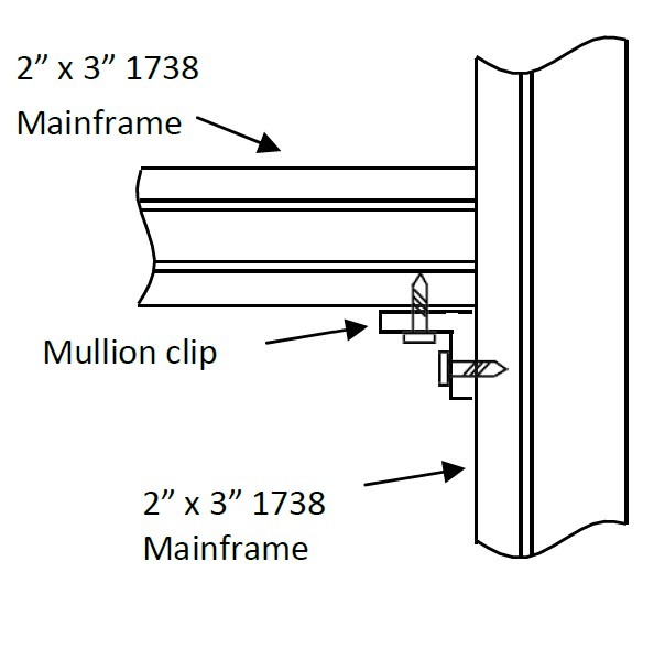
Installing Mullion Clips
Attach one of the supplied mullion clips to the 2" x 3" vertical framing member at the desired height.
Place your cut piece of 2" x 3" horizontal framing on top of this clip and fasten the clip to the underside of the horizontal piece.
Before installing the clip on the opposite side, place a level on the horizontal piece to ensure the mullion is perfectly straight.
Once level, install the second mullion clip to secure the other side.
Mullion clips are color-matched to your room. If unpainted clips were provided, you may spray them with the supplied touch-up paint (if desired) before installing the screen mesh in later steps.
Chair Rail Installation (2" and 3" Systems)
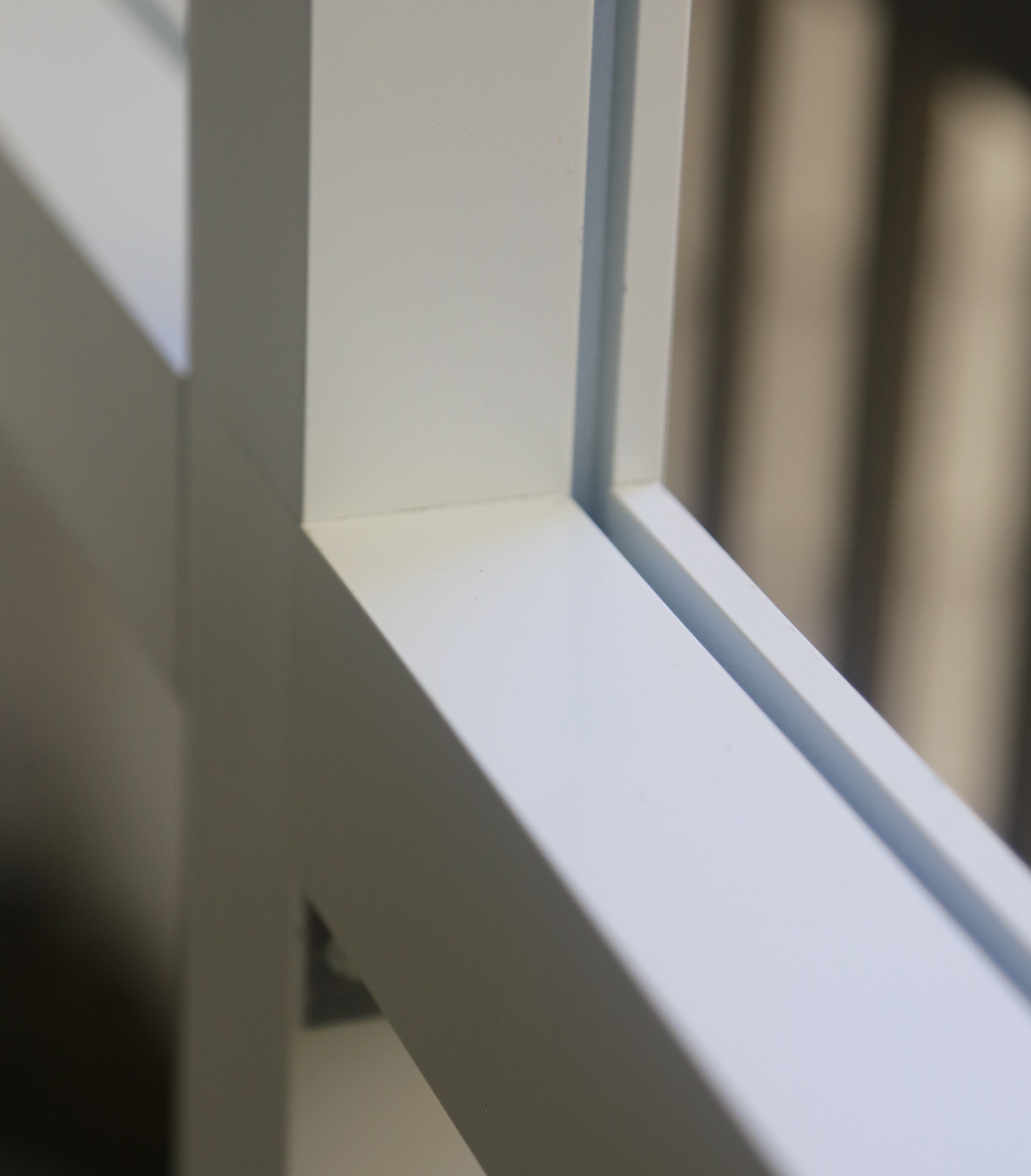
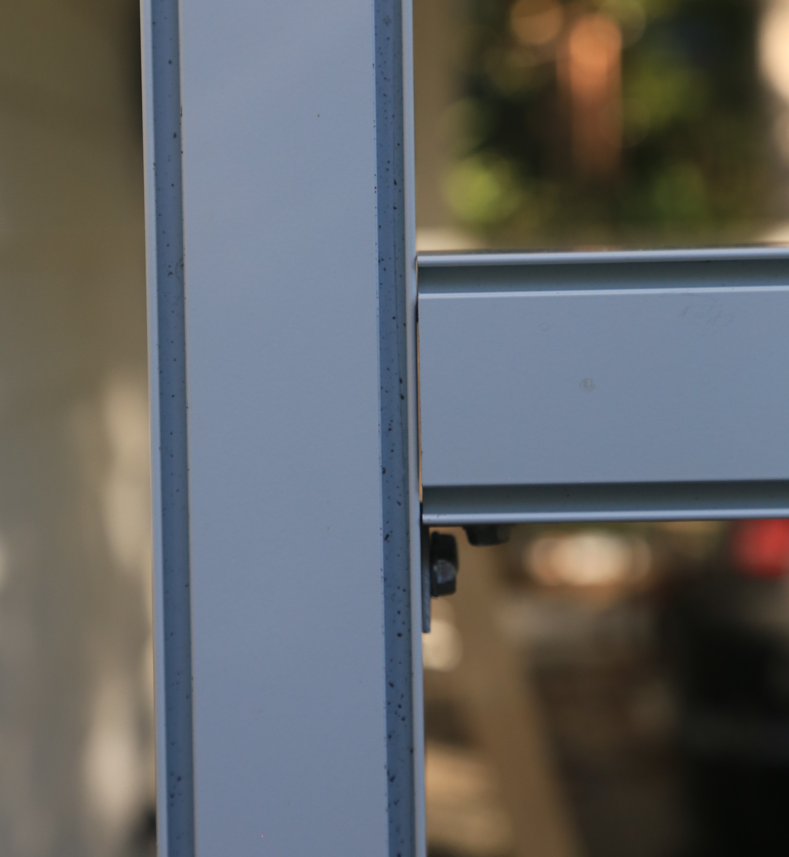
The images below show two views of a properly installed chair rail on a 2" system. The configuration for the 3" system is identical.
Left image: Correct installation where the kickplate grooves align on the inside of the posts.
Right image: Correct installation for an outside screen configuration, where the screen spline grooves align properly.
Install Kickplate (where applicable)
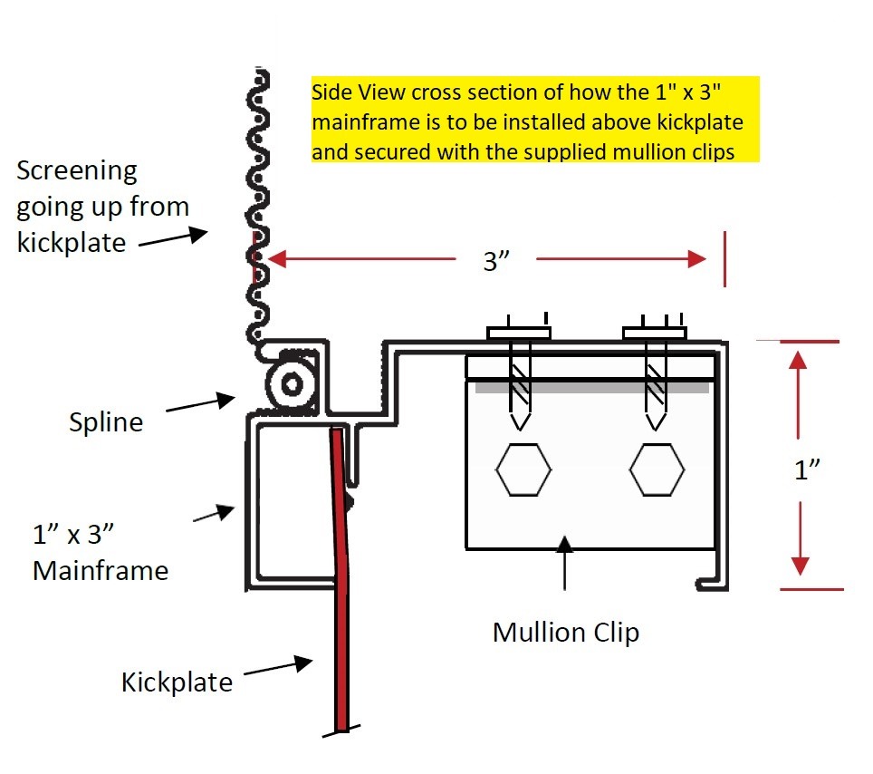
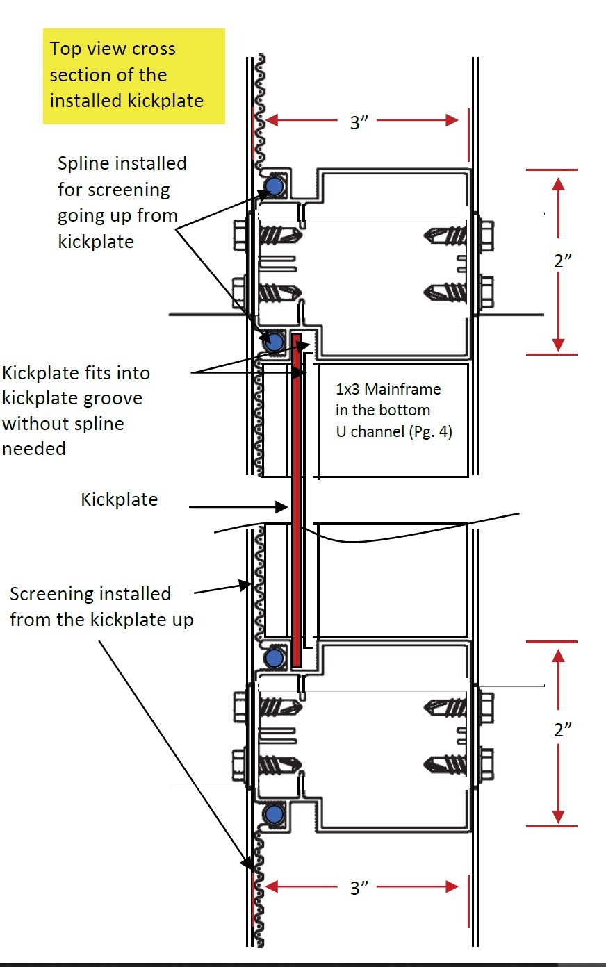
#Kickplate is typically installed with a 1x3 mainframe securing it in place, as shown in this section.
For rooms with openings greater than 54", a 2x3 mainframe will be provided instead. The installation process is the same as with the 1x3.
Refer to the room-specific sketch included with your order to confirm whether a 1x3 or 2x3 mainframe was quoted above your kickplate.
Installing Kickplate and Mainframe
Cut and Install Kickplate Sections
Cut (or score and snap with a utility knife) each kickplate section.
Sections should be 3/8" to 3/4" longer than the opening width between the vertical framing to account for the depth of the grooves.
Slide the kickplate into place (see second illustration on the right).
- Tip: Kickplate is shipped in a coiled roll. For easier installation, cut each section to size and allow it to flatten before placing it into the grooves.
Fit the 1x3 (or 2x3) Mainframe
Measure the opening above the kickplate, then cut the 1x3 (or 2x3) to fit between the vertical framing members.
Temporarily set the mainframe over the kickplate and confirm the kickplate slides fully into the groove (see first illustration on the right).
Install Mullion Clips
With the mainframe in place, slide a mullion clip under the extrusion where it meets each vertical framing member.
Mark the spot with a pen at the end of each clip.
Remove the mainframe and fasten the clips (one per side) to the vertical framing members.
As a guide: the top of each clip should sit about 1/4" above the top of the kickplate.
Account for Slope
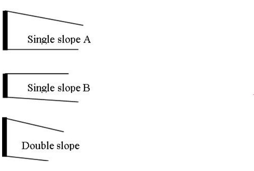
To keep the top of the kickplates even across all openings, use a string line stretched across the full width of the room.
The bottom of each kickplate can then be trimmed as needed to match the slope of the ceiling, floor, or both.
Installing the 1x3 Mainframe on Kickplate
Using the “single slope B” example:
If you install the 1x3 mainframe on top of the kickplate so it runs parallel to the roof line, the “outside” vertical measurement of the kickplate will gradually increase as you move from the house wall toward the front of the installation.
Alternatively, if you run the kickplate parallel to the deck or patio surface, the “outside” vertical measurement of the top screen section will gradually increase as you move away from the house wall toward the front.
Once positioned, place the 1x3 mainframe onto the mullion clips you installed earlier. Fasten it in place by driving the supplied self-tapping hex head Tek screws down through the top of the extrusion into the clips.
Note: If your room is ordered with a double-height kickplate, repeat the process a second time to achieve full height. In this case, the 1x3 mainframe will be installed above both kickplate panels within each opening.
Install Screening
#Using the supplied screen, spline, and spline roller, install screening in all openings created during construction. If previous steps were completed correctly, each opening should have visible spline grooves around the entire perimeter.
If any opening is missing a groove, review the appropriate section of the manual before continuing.
For rooms without a chair rail (or with only a kickplate), there will be one opening per section to screen. For rooms with a chair rail, you will need to screen both the upper and lower sections. The small opening above the door must also be screened.
Begin by rolling the spline and screen into the vertical grooves first. This helps manage screen tension at the midpoint of the vertical installation.
Once both sides are started, have a second person apply light inward pressure on the screen while you roll in the spline.
To prevent the spline from pulling the screen too tight, lightly drag the tip of your finger along the screen just ahead of the spline roller.
Screening Instructions
Begin by screening side to side first, pulling the screen taut but not overly tight.
Once the sides are secure, finish the section by rolling the spline and screen into the horizontal spline grooves.
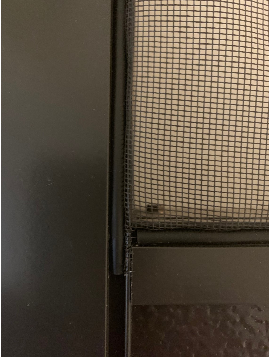
Use four separate spline pieces per section rather than one continuous length. Each piece should butt closely against the next, but they will not connect, since the horizontal and vertical grooves do not meet (see photo to the right).
After installing the spline, trim away any excess screen by carefully running a sharp blade (razor or utility knife) along the back edge of the spline.
Important: Take extra care not to over-tighten the screen vertically (up and down). Pulling it too tight may cause the horizontal center bar to bow or warp out of alignment.
Tips for Installing the 3" Screen Wall Kit
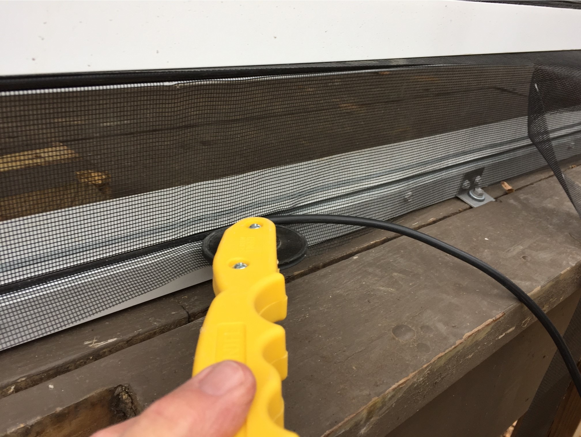
The 3" system uses a flat spline (unlike the round spline in the 2" system). For best results, position the spline with the narrow edge facing into the groove, then roll it in. It will lock securely in place for an excellent hold.
In cooler temperatures (below 50°F), the spline can become stiff and harder to install. To make it more flexible, warm it with a hair dryer or keep the roll inside your jacket sleeve and feed it out as you install.
For large openings, or if you have difficulty keeping the spline in place, spline clips are available to make installation easier.
Congratulations!
We’re delighted to welcome you to years of worry-free enjoyment, with lasting protection from bugs and the elements.
If you ever have questions or need support, our team is just a call away at 1-800-922-4760 (toll-free).